A related question is a question created from another question. When the related question is created, it will be automatically linked to the original question.
If you have a related question, please click the "Ask a related question" button in the top right corner. The newly created question will be automatically linked to this question.
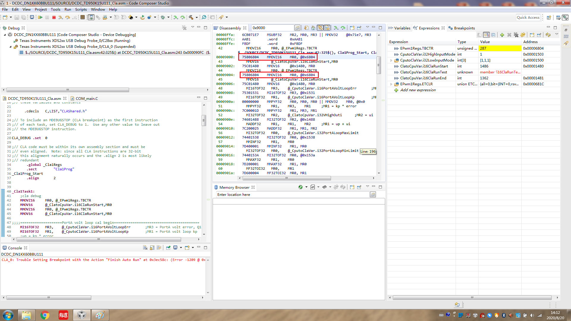
Q3 is almost same as Q2, the address of CputoClaVar.i32HighInputMode is 0x1503, the value is 1, but in Disassembly, read the value of 0x1506 the compare with MR0(0x02).
/*
// TI File $Revision: /main/3 $
// Checkin $Date: February 23, 2009   13:44:16 $
//###########################################################################
//
// FILE:	F2808.cmd
//
// TITLE:	Linker Command File For F2808 Device
//
//###########################################################################
// $TI Release: DSP2803x C/C++ Header Files V1.10 $
// $Release Date: July 27, 2009 $
//###########################################################################
*/

/* ======================================================
// For Code Composer Studio V2.2 and later
// ---------------------------------------
// In addition to this memory linker command file,
// add the header linker command file directly to the project.
// The header linker command file is required to link the
// peripheral structures to the proper locations within
// the memory map.
//
// The header linker files are found in <base>\DSP2803x_Headers\cmd
//
// For BIOS applications add:      DSP2803x_Headers_BIOS.cmd
// For nonBIOS applications add:   DSP2803x_Headers_nonBIOS.cmd
========================================================= */

/* ======================================================
// For Code Composer Studio prior to V2.2
// --------------------------------------
// 1) Use one of the following -l statements to include the
// header linker command file in the project. The header linker
// file is required to link the peripheral structures to the proper
// locations within the memory map                                    */

/* Uncomment this line to include file only for non-BIOS applications */
/* -l DSP2803x_Headers_nonBIOS.cmd */

/* Uncomment this line to include file only for BIOS applications */
/* -l DSP2803x_Headers_BIOS.cmd */

/* 2) In your project add the path to <base>\DSP2803x_headers\cmd to the
   library search path under project->build options, linker tab,
   library search path (-i).
/*========================================================= */

/* Define the memory block start/length for the F28035
   PAGE 0 will be used to organize program sections
   PAGE 1 will be used to organize data sections

   Notes:
         Memory blocks on F2803x are uniform (ie same
         physical memory) in both PAGE 0 and PAGE 1.
         That is the same memory region should not be
         defined for both PAGE 0 and PAGE 1.
         Doing so will result in corruption of program
         and/or data.

         L0 memory block is mirrored - that is
         it can be accessed in high memory or low memory.
         For simplicity only one instance is used in this
         linker file.

         Contiguous SARAM memory blocks or flash sectors can be
         be combined if required to create a larger memory block.
*/
_Cla1Prog_Start = _Cla1funcsRunStart;

// Define a size for the CLA scratchpad area that will be used
// by the CLA compiler for local symbols and temps
// Also force references to the special symbols that mark the
// scratchpad are.
// CLA_SCRATCHPAD_SIZE = 0x100;
--undef_sym=__cla_scratchpad_end
--undef_sym=__cla_scratchpad_start

MEMORY
{
PAGE 0:    /* Program Memory */
           /* Memory (RAM/FLASH/OTP) blocks can be moved to PAGE1 for data allocation */
   RAML0_PRG   : origin = 0x008000, length = 0x000500		/* on-chip RAM block */
   RAML0BOOT_PRG   : origin = 0x008c00, length = 0x000020	/* on-chip RAM block */
   RAMCLA_PRG  : origin = 0x009000, length = 0x001000      // for cla


   OTP         : origin = 0x3D7800, length = 0x000400     /* on-chip OTP */
   /*APPVEC 	   : origin = 0x3F0000, length = 0x000010*/
   /*FLASH	   : origin = 0x3F0010, length = 0x005FEF*/
   APPVEC 	   : origin = 0x3E8000, length = 0x000010
   FLASH_APP   : origin = 0x3E8010, length = 0x00DFEF
   APPCRC	   : origin = 0x3F5FFF, length = 0x000001
   FLASHA_PFC	: origin = 0x3F6000, length = 0x000FFF
   BOOTVEC 	   : origin = 0x3F7000, length = 0x000050
   RAMFLASH	   : origin = 0x3F7050, length = 0x000020
   LIB_FLASH   : origin = 0x3F7070, length = 0x0002E0
   /*LIB_FLASH   : origin = 0x3F7070, length = 0x000210*/

   FLASHA_BOOT  : origin = 0x3F7350, length = 0x000C30     /* on-chip FLASH */
   /*FLASHA_BOOT  : origin = 0x3F7280, length = 0x000D00*/
   CSM_RSVD    : origin = 0x3F7F80, length = 0x000076     /* Part of FLASHA.  Program with all 0x0000 when CSM is in use. */
   BEGIN       : origin = 0x3F7FF6, length = 0x000002     /* Part of FLASHA.  Used for "boot to Flash" bootloader mode. */
   CSM_PWL     : origin = 0x3F7FF8, length = 0x000008     /* Part of FLASHA.  CSM password locations in FLASHA */

   IQTABLES    : origin = 0x3FE000, length = 0x000B50     /* IQ Math Tables in Boot ROM */
   IQTABLES2   : origin = 0x3FEB50, length = 0x00008C     /* IQ Math Tables in Boot ROM */
   IQTABLES3   : origin = 0x3FEBDC, length = 0x0000AA	  /* IQ Math Tables in Boot ROM */

   ROM         : origin = 0x3FF27C, length = 0x000D44     /* Boot ROM */
   RESET       : origin = 0x3FFFC0, length = 0x000002     /* part of boot ROM  */
   VECTORS     : origin = 0x3FFFC2, length = 0x00003E     /* part of boot ROM  */

PAGE 1 :   /* Data Memory */
           /* Memory (RAM/FLASH/OTP) blocks can be moved to PAGE0 for program allocation */
           /* Registers remain on PAGE1                                                  */

   RAMM0       : origin = 0x000000, length = 0x000400     /* on-chip RAM block M0 */
   RAMM1       : origin = 0x000400, length = 0x000200     /* on-chip RAM block M1 */
   RAMM1_EBSS  : origin = 0x000600, length = 0x000100     /* on-chip RAM block M1 */
   /*RAML:origin = 0x000700, length = 0x0000E0 for IsrVariable */
   RAML0_DATA  : origin = 0x008500, length = 0x000300	  // for .ebss
   RAML1_CLA   : origin = 0x008800, length = 0x000400     // for cla data
   RAML2_DATA  : origin = 0x008c20, length = 0x000320       // for .ebss

}

/* Allocate sections to memory blocks.
   Note:
         codestart user defined section in DSP28_CodeStartBranch.asm used to redirect code
                   execution when booting to flash
         ramfuncs  user defined section to store functions that will be copied from Flash into RAM
*/

SECTIONS
{

   /* Allocate program areas: */
   .cinit              : > FLASH_APP      PAGE = 0
   .text               : > FLASH_APP      PAGE = 0
   .init			   : LOAD = FLASHA_BOOT      PAGE = 0
	{
		//DSP2803x_Adc.obj (.text)
		//DSP2803x_EPwm.obj (.text)
		//DSP2803x_InitPeripherals.obj (.text)
		DSP2803x_PieCtrl.obj (.text)
		DSP2803x_PieVect.obj (.text)
		DSP2803x_CpuTimers.obj (.text)
		DSP2803x_DefaultIsr.obj (.text)
		DSP2803x_ECan.obj (.text)
		DSP2803x_Gpio.obj (.text)
		DSP2803x_I2C.obj (.text)
		DSP2803x_SCI.obj (.text)
		DSP2803x_MemCopy.obj (.text)
		DSP2803x_SysCtrl.obj (.text)
   }
   .init2				: LOAD = FLASHA_PFC         PAGE = 0
    {
		DCDC_DN1KK60BBU111_PFCSciDownload.obj (.text)
    }
   .cal  : > LIB_FLASH      PAGE = 0
	{
		-lrts2800_ml.lib <fd_mpy.obj u_div.obj memcpy.obj
		l_div.obj fd_tol.obj fs_tofd.obj fs_tou.obj
		boot.obj exit.obj _lock.obj> (.text)

		-lrts2800_ml.lib <exit.obj _lock.obj> (.cinit)

	}

   codestart           : > BEGIN       PAGE = 0

   bootramfuncs        : LOAD = RAMFLASH,
                         RUN = RAML0BOOT_PRG,
                         LOAD_START(_BootRamfuncsLoadStart),
                         LOAD_END(_BootRamfuncsLoadEnd),
                         RUN_START(_BootRamfuncsRunStart),
                         PAGE = 0
   IsrRamfuncs         : LOAD = FLASH_APP,
                         RUN = RAML0_PRG,
                         LOAD_START(_IsrRamfuncsLoadStart),
                         LOAD_END(_IsrRamfuncsLoadEnd),
                         RUN_START(_IsrRamfuncsRunStart),
                         PAGE = 0

   .appvec             : > APPVEC   PAGE = 0
   appcrc              : > APPCRC   PAGE = 0
   .bootvec            : > BOOTVEC  PAGE = 0
   FlashBoot           : > FLASHA_BOOT      PAGE = 0

   csmpasswds          : > CSM_PWL     PAGE = 0
   csm_rsvd            : > CSM_RSVD    PAGE = 0

   /* Allocate uninitalized data sections: */
   .stack              : > RAMM1       PAGE = 1
   .ebss               : >> RAML0_DATA|RAML2_DATA|RAMM1_EBSS      PAGE = 1
   RamData             : > RAMM0       PAGE = 1
   /*.esysmem            : > RAMM0       PAGE = 1 */
   /* Initalized sections go in Flash */
   /* For SDFlash to program these, they must be allocated to page 0 */
   .econst             : > FLASH_APP      PAGE = 0
   .switch             : > FLASH_APP      PAGE = 0
   .const              : > FLASH_APP      PAGE = 0

   /* Allocate IQ math areas: */
   IQmath              : > FLASH_APP       PAGE = 0                  /* Math Code */
   IQmathTables        : > IQTABLES,   PAGE = 0, TYPE = NOLOAD

      //for cla
    Cla1Prog           : LOAD = FLASH_APP,
                         RUN = RAMCLA_PRG,
                         LOAD_START(_Cla1funcsLoadStart),
                         LOAD_END(_Cla1funcsLoadEnd),
                         RUN_START(_Cla1funcsRunStart),
                         PAGE = 0

   .bss_cla		: > RAML1_CLA,       PAGE = 1
   .scratchpad          : > RAML1_CLA,       PAGE = 1
   .const_cla           : > RAML1_CLA,       PAGE = 1

   CLAscratch           :
                         { *.obj(CLAscratch)
                         . += CLA_SCRATCHPAD_SIZE;
                         *.obj(CLAscratch_end) } > RAML1_CLA,
                         PAGE = 1
   /* .reset is a standard section used by the compiler.  It contains the */
   /* the address of the start of _c_int00 for C Code.   /*
   /* When using the boot ROM this section and the CPU vector */
   /* table is not needed.  Thus the default type is set here to  */
   /* DSECT  */
   .reset              : > RESET,      PAGE = 0, TYPE = DSECT
   vectors             : > VECTORS     PAGE = 0, TYPE = DSECT
Check the map file, I think the address of EpwmRegsfile is normal.
Then compare my project with example project in C2000ware,
The address of EPwmRegs in two project in Expressions is identical.
Q1, In Disassembly, in my project, 32-bit instruction to read register value, but in C2000ware project, 16-bit instruction to read same register value. I think this difference lead to incorrect register address in my project.
Q2, More MNOP instruction in my project, this two project have same configure on the opt_level and opt_for_speed .
Q3 ls related to data type define ,I change int16 to int16_t, the variable address is correct.
My apologies. I missed question 3 previously. Yes, using standard C99 datatypes is recommended. The CLA integer is a 32-bit while on C28x it is 16. If the compiler sees the standard type (int16_t) then it will handle it as such on both the C28x and the CLA.
Q1, In Disassembly, in my project, 32-bit instruction to read register value, but in C2000ware project, 16-bit instruction to read same register value. I think this difference lead to incorrect register address in my project.
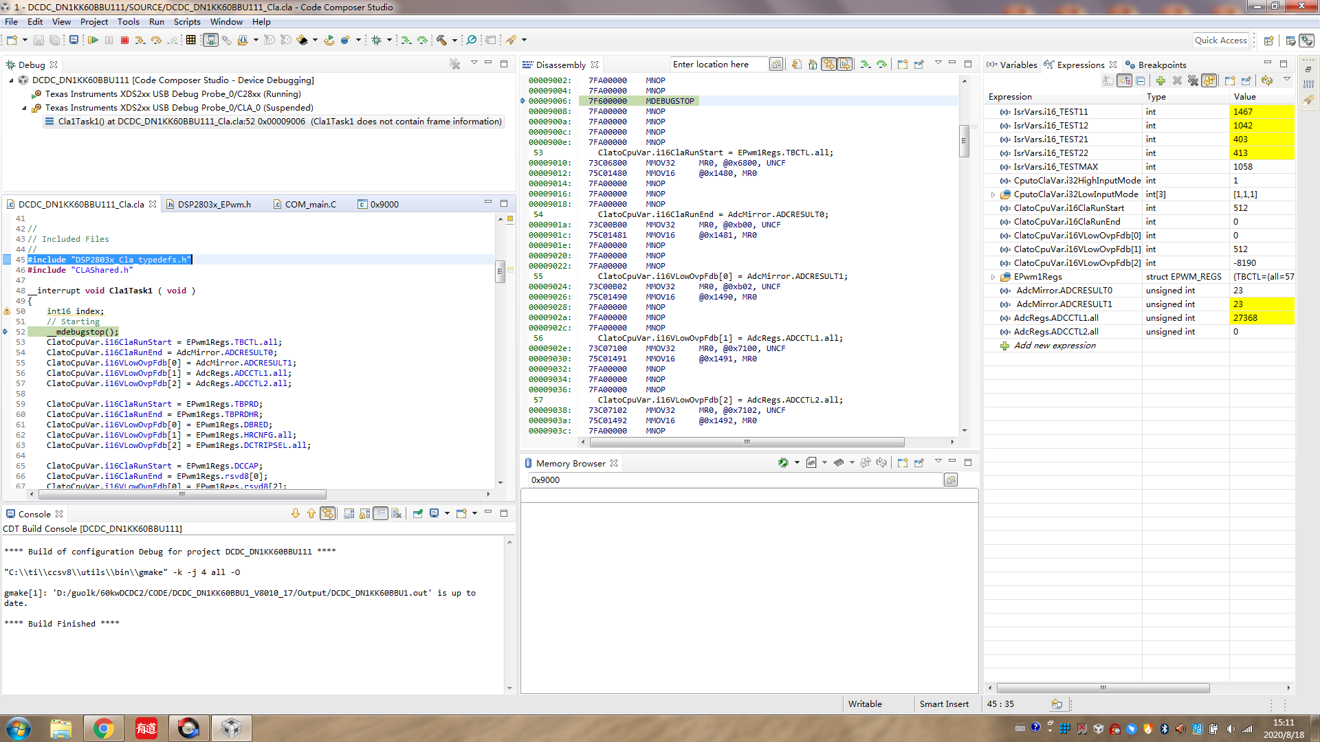
Are you including the file DSP2803x_Cla_typedefs.h for the CLA code? In our older examples instead of using C99 datatypes we used this file to describe the size of variables to the compiler. You should see this include in the C2000ware examples as well.
First, add #include "DSP2803x_Cla_typedefs.h" to first line of CLA file. In Disassembly, 16-bit Register variable is still read use 32-bit instruction.
I took an example from C2000Ware - the acos example, and added the following lines to try and reproduce the issue. These are the only lines I added - all of the #includes are as I found them.
In this project, the acos.cla has the following include. This includes all of the peripheral header files and the CLA types.
//
// Included Files
//

#include "DSP28x_Project.h"
If I understand, you have a working project that you can check against? If that is the case, check that the #includes are the same in your project. You can try adding the structure to the working project as an experiment.
How is the struct defined in the non-working code?
Another suggestion is to check these FAQs and see if they apply:
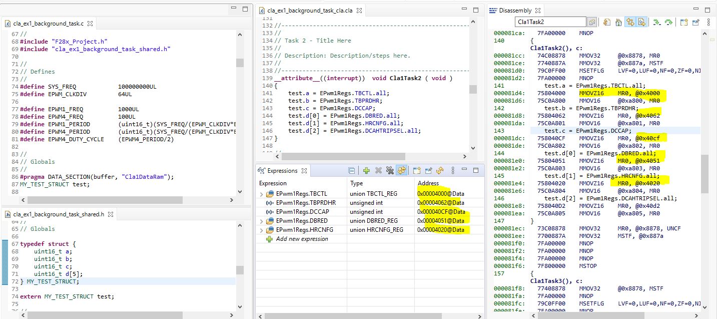
I've been trying to reproduce the issue but have not been able to. Note: Because I do not have a F2803x with me (I am working from home due to COVID) I tried this on a F28004x. The same would apply to your device except the PWM registers are at a different memory address. The disassembly instructions match the expressions window regarding the address.
I have detailed my steps below. If this does not help resolve the problem, please work with Brian Wang to send me a small test case that reproduces the issue?
1) Created a structure, similar to yours, as shown. This goes in the shared.h header file:
4) Observe disassembly and Expressions window match addresses. Note: 28004x has different memory locations for the ePWM registers than the F2803x you are using.
Can you provide a very simple, small, testcase based on one of TI's examples (C2000Ware/device_support) that shows the issue? It will really help if I can reproduce the problem.
Also please include which compiler version you are using and your compile options.
Exclude #include "DSP280x_Device.h" in CLA C source code, only #include "CLAShared.h" && #include "DSP2803x_EPwm.h" , the Epwm Register address in disassembly is correct.
CLAShared.h include the variables used in CLA C code, define by me.
I compare my DSP280x_Device.h with file in C2000ware, can not find what lead the Register address in Disassembly incorrect.