This thread has been locked.

If you have a related question, please click the "Ask a related question" button in the top right corner. The newly created question will be automatically linked to this question.

TMS320F28034: channel crosstalk

Part Number: TMS320F28034
Other Parts Discussed in Thread: INA240

Hi,

my customer is using F28034's ADC to sample 8 INA240s' output. INA240's output is connected to ADC pin of F28034 through 1kohm plus a 10ohm,1nF RC filter shown below.

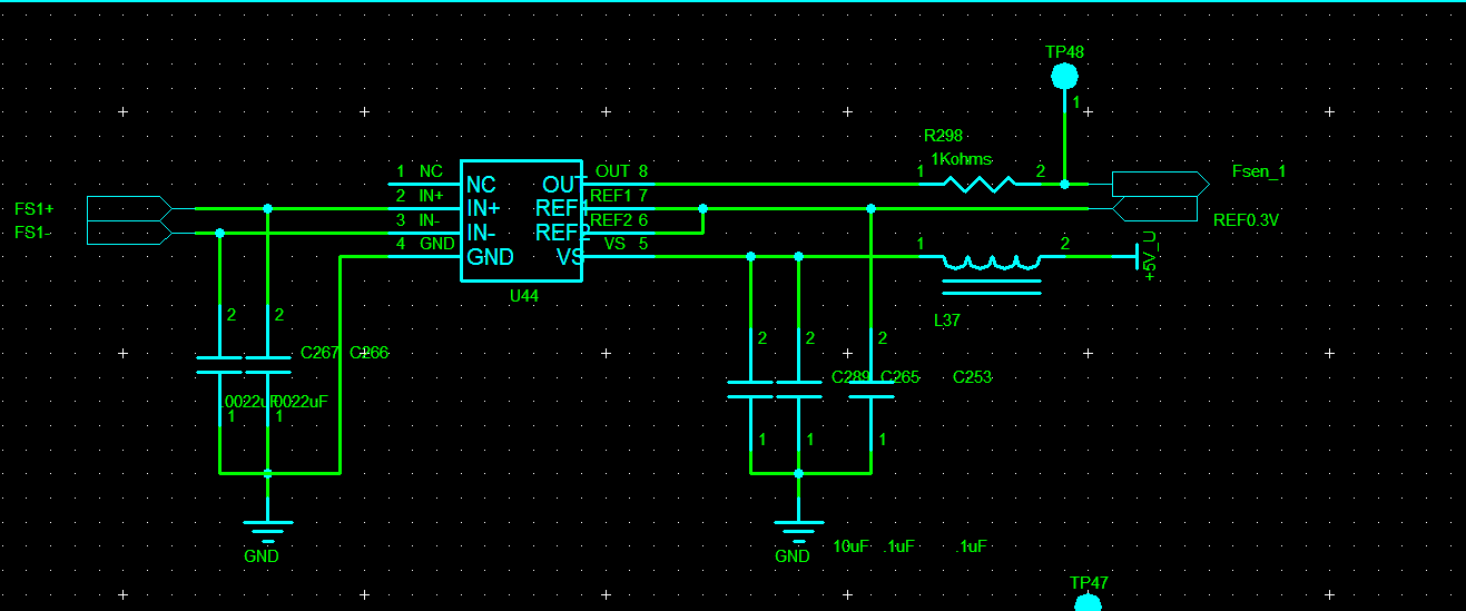
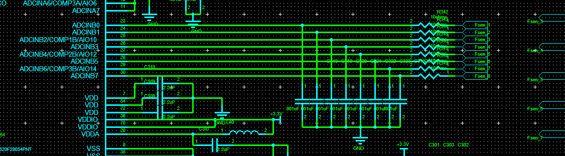
We sample from ADCINB0-ADCINB7.

When only first channel INA240's output is 1V, all other channels output is 0V, we could observe about 0.1V on channel 2 "ADCINB1". We can observe this 0.1V through multimeter on F28034's pin, and the ADC result also shows  it's 0.1V.

When only second channel INA240's output is 1V, all other channels output is 0V, we could observe about 0.1V on channel 3 "ADCINB2". We can observe this 0.1V through multimeter on F28034's pin, and the ADC result also shows  it's 0.1V.

We tried to replace the 1kohm to 0ohm and unsolder the 1nF filter cap, the problem is still there.

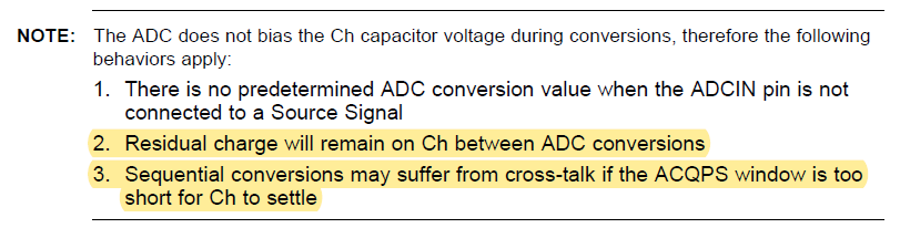
Then we extend the S+H window to 64 cycles, the 0.1V becomes around 0.05V which is still big.

Then we keep S+H window to 64 cycles, and sample twice, dump the first ADCRESULT,  0.1V becomes very small and the result is acceptable.

What may cause this problem? How can we keep the S+H window short and solve the problem?

  • Howard,

    For reference, I used the ADC ACQPS guidelines from the F2806x TRM to double-check your reported errors on F2803x. I would not expect the component values in place to produce this much error.

    Since you are able to measure 100mV using a multimeter, it sounds like this is a DC voltage coming from the sensor circuit rather than an ADC-induced glitch. Is the 100mV offset still present on the sensor circuit output if the ADC channel is disconnected by removing the 10Ω resistor?

    -Tommy

  • Hi,

    we tried to remove 10ohm resistor, then only 1nF cap is connected to the ADC input pin of F28034.

    When we monitor the voltage on this pin, it's not stable, it will variate, I guess floating the ADC input of F28034 is not okay.

    So we cannot figure out the problem is caused by INA240 itself or F28034's crosstalk.

  • Howard,

    Are you saying that the INA240 output itself will fluctuate if the ADC pin is not connected?  If so, that would suggest that the INA240 is not stable.

    To be clear, my intent was to measure the INA240 output using a scope or multimeter, not sample the floating ADC channel.

    -Tommy

  • No,

    I'm saying the ADC input pin will fluctuate.

    We are measuring with a multimeter.

  • Howard,

    Voltage fluctuations on ADC pins is common when they are not driven.  This is not a problem by itself.

    Can you inspect the voltage of the INA240 output when it is not connected to the ADC?

    -Tommy

  • Tommy,

    INA240 output of the next channel is stable and will not be affected by last channel when it's not connected to ADC.

    So the problem should be caused by F28034 itself.

    But we also do a test by connecting F28034's next ADC input to a DC source, for example 1V, the ADC result is correct and it will not be affected by last channel's INA240's value. That makes things confused.

  • Howard,

    I am asking you to validate the signal chain by measuring the INA240 output when it is not connected to the ADC channel. There is not enough information to determine where the observed offset is coming from.

    -Tommy

  • Tommy,

    sorry that I haven't make it clear.

    I have disconnect the channel 2's INA240 output with the ADC input of F28034 by removing the 10ohm.

    And with the same procedure, we sample ADCINB0 (which is connected to 1st channel INA240's output) and then ADCINB1(which is now disconnected from 2nd channel INA240's output).

    And by measuring the 2nd channel INA240's output with multimeter, there is no offset.

    If we connect 2nd channel INA240's output to ADCINB1 again, there is offset, and the offset is related to the voltage amplitude of 1st channel INA240's output.

  • Howard,

    Thanks for clarifying.  For background, I do expect some small amount of crosstalk between sequential conversions of channels that share a S+H capacitor, as described in this note in the TRM:

    However, the component values and ACQPS settings in use should be able to overcome the residual charge on the 1.6pF sampling capacitor.

    My thoughts based on your observation that a second sample is more accurate led me to consider these possibilities, but they don't quite make sense:

    1. The Initial Conversion advisory -- but the assumption for this issue is that the error is in the conversion stage, not S+H capacitor corruption, so measuring a 100mV offset voltage on the channel doesn't quite match,
    2. Cross-talk from residual S+H charge -- but the 1nF capacitor should be able to bring the S+H capacitor within about 7-LSB of the input voltage by itself, which would look more like 6mV of error based on the F2806x ACQPS guidelines

    One scenario that would make sense is if the 1nF filtering cap was defective and wasn't providing the expected assistance with charging the S+H capacitor in a short amount of time.  Does replacing the filter capacitor or increasing its value help?

    -Tommy