Hello, community,
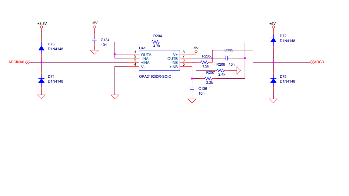
I have a problem getting data from DAC output of 377D. In my DSP board, there are three opamp circuits. DACOUTA(ADCINA0), DACOUTB and DACOUTC are connected to the input of these opamp circuits. ADC0 is the output of the opamp circuit. One of the circuit schematics is below:
In the CCS project, the code for calling DAC and SetDAC are below:
void CallDAC(int DACchannel, float val, float maxRange , int direction)
{
	unsigned int res = 0;

	if(direction == 0)
	{
		res = (unsigned int)((val/maxRange)*4095.0);
	}
	else
	{
		val = (val + maxRange)/2;
		res = (unsigned int)((val/maxRange)*4095.0);
	}
	if(res > 4095) res = 4095;
	if(res < 1)val = 0;

	DACsel[DACchannel]->DACVALS.bit.DACVALS = res;
}
void SetDAC(void)
{
 EALLOW;
 //reference voltage set as same as ADC ref (VREF)
 DACsel[DACA]->DACCTL.bit.DACREFSEL = REFERENCE_VREF;
 DACsel[DACB]->DACCTL.bit.DACREFSEL = REFERENCE_VREF;
 DACsel[DACC]->DACCTL.bit.DACREFSEL = REFERENCE_VREF;
 //Enable DAC ,,powering up DAC
 DACsel[DACA]->DACOUTEN.bit.DACOUTEN = 1;
 DACsel[DACB]->DACOUTEN.bit.DACOUTEN = 1;
 DACsel[DACC]->DACOUTEN.bit.DACOUTEN = 1;
 EDIS;
 //set initial output value 0
 DACsel[DACA]->DACVALS.bit.DACVALS = 0;
 DACsel[DACB]->DACVALS.bit.DACVALS = 0;
 DACsel[DACC]->DACVALS.bit.DACVALS = 0;
 //wait for turn on DAC module
 DELAY_US(10);
}
and in the header function, DAC channels are defined as follows.
extern volatile struct DAC_REGS *DACsel[4];
#define DACA 1
#define DACB 2
#define DACC 3
#define REFERENCE_VDAC 0
#define REFERENCE_VREF 1
extern void SetADC(void);
extern void SetDAC(void);
extern void CallDAC(int DACchannel, float val, float maxRange , int direction);
In the main function I put the SetDAC into main(void) function as follows. ( I did not included all codes here for clear explanations).
int main(void)
{

	DINT;
	InitSysCtrl();
	InitGpio();
	InitSWGpio();
	InitEPwmGpio();
	InitEQepGpio();
	InitSCIgpio();
	InitRelayGpio();
	InitCANGpio();
        SetADC();
	SetDAC();
	SetPWM();
	SetRelay();
	SetCAN();
	InitPieCtrl();
........
I put the CallDAC function into the ePWM interrup funcion as :
interrupt void EPWM1_isr(void)
{
.
.
.
CallDAC(DACA, ind_val1.inverterVDi, 3 , 1);
.
.
ind_val1.inverterVDi is a DC variable, a typical value is 30 Volts DC voltage calculated using three-phase voltage measurement values. These values are taken from ADCBresult regs.
I connected oscilloscope plus prob to DACA output (ADC0 in the above figure) and ground prob to dc ground (ground in the above figure). When I run the DSP board, the controller and system are working well but I could not see the ind_val1.inverterVDi value in the scope. I see only noise around zero offset.
Do you have any idea what should be the problem ?
What should be the maxRange value ?
sorry for the long explanations.

Best regards,


