


Part Number: TMS320F280025C
Hi Team,
My customer are using F280025C for motor control using FAST observer with their own board, motor parameter identified is ok to calculate correct Ls, Rs, in the speed loop control mode, the motor can run well less than 1200Hz(electrical speed) with Input voltage about 40V, but once over 1200Hz, the motor control is not stable and will lead to over current. the current waveform is show as below when motor speed over 1200Hz.

In order to find the root cause, use the FAST angle and open loop control without speed loop and current loop, that is set a Vq to spin motor and using FAST angle for clark and park transform,
below are the waveform of FAST angle at 500Hz when using F280025C, which is good.
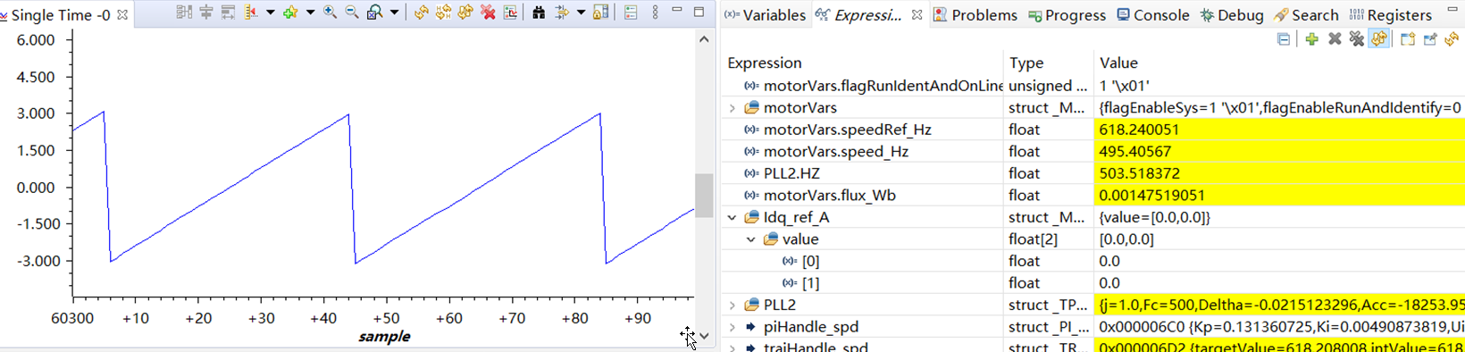
When the speed reach 750Hz, the waveform of FAST angle is not good and have distortions.
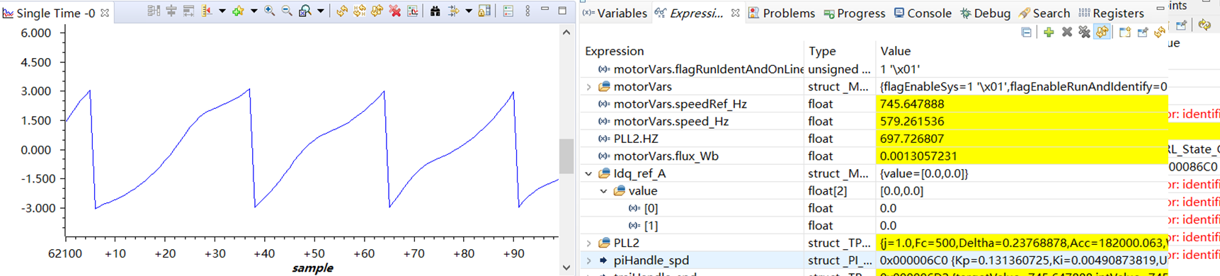
When the speed reach 980Hz, the waveform of FAST angle have more distortions, and will go to over current when speed over 1200Hz.

However, customer also used to design a F28027F board and have the same hardware parameter and software parameter, with F28027F FAST, they can run over 1500Hz, when work in the same open loop mode, it seem the FAST angle is accurate at about 1KHz as below showed.

Both of F280025C and F28027F board are using the same hardware parameters:
|
28027F |
280025C |
|
Current sample:3 resistor sample |
Current sample:3 resistor sample |
|
Base phase current:±330A |
Base phase current:±330A |
|
Base phase voltage:68.14V |
Base phase voltage:68.14V |
|
phase voltage filter cut off frequency: 389Hz |
phase voltage filter cut off frequency: 389Hz |
|
Driver IC number:3 |
Driver IC number:1 |
|
Layout: one board including control and power circuit |
Layout: two separate board for control and power circuit |
Question is:
1. any possible reason that cause F280025C fail to control at high speed like 1200Hz and the FAST angle become inaccuracy? customer's target goal is to achieve 1500Hz or higher.
2. Did we have test F280025C FAST at high speed that over 1.5KHz?
