


Hi Team,
I have a question regarding the high-resolution dead-band functionality on ePWM output B, hopefully you can help me out here.
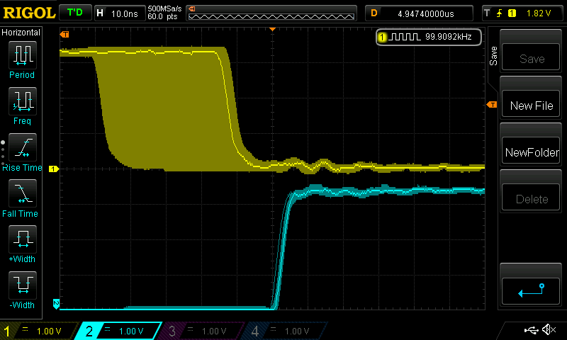
I have configured the dead-band module to active high complementary mode: both FED and RED use EPWM1A for input, FED output is inverted. FED delay is 10, resulting in a 50-ns dead-band (half cycle mode). In my code the duty cycle is set to 50%, and I am sweeping CMPAHR from 0 to 255, as seen on the scope image below (OutA on Ch1, yellow). Meanwhile, OutB (Ch2, blue) rising edge is not moving. Is this the expected behavior, shouldn't OutB rising edge move and maintain 50-ns dead-band all the time?
Below is my initialization code for the ePWM, am I missing something here? I am able to change the dead-band while debugging, both coarse and fine part, but the dead-band is always with regards to the coarse part of CMPA, ignoring the CMPAHR part.
void initEPWM() {
    SysCtl_disablePeripheral(SYSCTL_PERIPH_CLK_TBCLKSYNC); // Disable sync and clock to TB

    // Configure frequency, duty, phase, outputs
    EPWM_setTimeBasePeriod(EPWM1_BASE, EPWM1_TIMER_TBPRD); // Set timer period
    EPWM_setTimeBaseCounter(EPWM1_BASE, 0U); // Set timer initial value
    EPWM_setPhaseShift(EPWM1_BASE, 0U); // No phase shift
    EPWM_setTimeBaseCounterMode(EPWM1_BASE, EPWM_COUNTER_MODE_UP); // Set UP counter mode
    EPWM_disablePhaseShiftLoad(EPWM1_BASE); // No phase shift load
    EPWM_setClockPrescaler(EPWM1_BASE,EPWM_CLOCK_DIVIDER_1,EPWM_HSCLOCK_DIVIDER_1); // Set timer clock prescaler to 1:1
    EPWM_setCounterCompareValue(EPWM1_BASE,EPWM_COUNTER_COMPARE_A,EPWM1_CMPA); // Set CMPA
    HRPWM_setHiResCounterCompareValueOnly(EPWM1_BASE,HRPWM_COUNTER_COMPARE_A,0); // Set CMPA.HR
    EPWM_setCounterCompareShadowLoadMode(EPWM1_BASE,EPWM_COUNTER_COMPARE_A,EPWM_COMP_LOAD_ON_CNTR_ZERO); // Enable double buffering for CMPA
    EPWM_setActionQualifierAction(EPWM1_BASE,EPWM_AQ_OUTPUT_A,EPWM_AQ_OUTPUT_HIGH,EPWM_AQ_OUTPUT_ON_TIMEBASE_ZERO); // PWMA output goes 1 on TB=0
    EPWM_setActionQualifierAction(EPWM1_BASE,EPWM_AQ_OUTPUT_A,EPWM_AQ_OUTPUT_LOW,EPWM_AQ_OUTPUT_ON_TIMEBASE_UP_CMPA); // PWMA output goes 0 on TB=CMPA

    // Configure dead time
    EPWM_setDeadBandCounterClock(EPWM1_BASE, EPWM_DB_COUNTER_CLOCK_HALF_CYCLE); // Half clock cycle used as unit for dead time
    EPWM_setDeadBandControlShadowLoadMode(EPWM1_BASE, EPWM_DB_LOAD_ON_CNTR_ZERO); // Enable double buffering
    EPWM_setDeadBandDelayMode(EPWM1_BASE, EPWM_DB_RED, true); // Enable rising edge delay
    EPWM_setDeadBandDelayMode(EPWM1_BASE, EPWM_DB_FED, true); // Enable falling edge delay
    EPWM_setFallingEdgeDeadBandDelayInput(EPWM1_BASE, EPWM_DB_INPUT_EPWMA); // EPWMA used for rising edge delay
    EPWM_setRisingEdgeDeadBandDelayInput(EPWM1_BASE, EPWM_DB_INPUT_EPWMA); // EPWMA used for falling edge delay
    EPWM_setDeadBandDelayPolarity(EPWM1_BASE, EPWM_DB_RED, EPWM_DB_POLARITY_ACTIVE_HIGH); // RED output (OutA path) is not inverted
    EPWM_setDeadBandDelayPolarity(EPWM1_BASE, EPWM_DB_FED, EPWM_DB_POLARITY_ACTIVE_LOW); // FED output (OutB path) is inverted
    EPWM_setDeadBandOutputSwapMode(EPWM1_BASE, EPWM_DB_OUTPUT_A, false); // No swap on OutA output
    EPWM_setDeadBandOutputSwapMode(EPWM1_BASE, EPWM_DB_OUTPUT_B, false); // No swap on OutB output
    EPWM_setFallingEdgeDelayCount(EPWM1_BASE, EPWM1_DTF); // Set rising edge delay
    EPWM_setRisingEdgeDelayCount(EPWM1_BASE, EPWM1_DTR); // Set falling edge delay

    // Configure HR
    HRPWM_setMEPEdgeSelect(EPWM1_BASE, HRPWM_CHANNEL_A, HRPWM_MEP_CTRL_FALLING_EDGE); // Set MEP to control falling edge on EPWMA
    HRPWM_setMEPControlMode(EPWM1_BASE, HRPWM_CHANNEL_A, HRPWM_MEP_DUTY_PERIOD_CTRL); // Set MEP to be controlled by CMPAHR
    HRPWM_setCounterCompareShadowLoadEvent(EPWM1_BASE, HRPWM_CHANNEL_A, HRPWM_LOAD_ON_CNTR_ZERO); // Enable double buffering
    HRPWM_setDeadbandMEPEdgeSelect(EPWM1_BASE, HRPWM_DB_MEP_CTRL_FED); // Set high resolution dead-band MEP control

    SysCtl_enablePeripheral(SYSCTL_PERIPH_CLK_TBCLKSYNC); // Enable sync and clock to TB
}
Thanks and regards,
Milos

