This thread has been locked.

If you have a related question, please click the "Ask a related question" button in the top right corner. The newly created question will be automatically linked to this question.

LAUNCHXL-F280049C: Lab IS03

Part Number: LAUNCHXL-F280049C


Hey TI - i am having problems running my blower in Lab IS06 (and above) so i went back to IS03 to see if i can understand what is going on.  Naturally, this lab opened up lots of questions.  I am hoping you may be able to help.

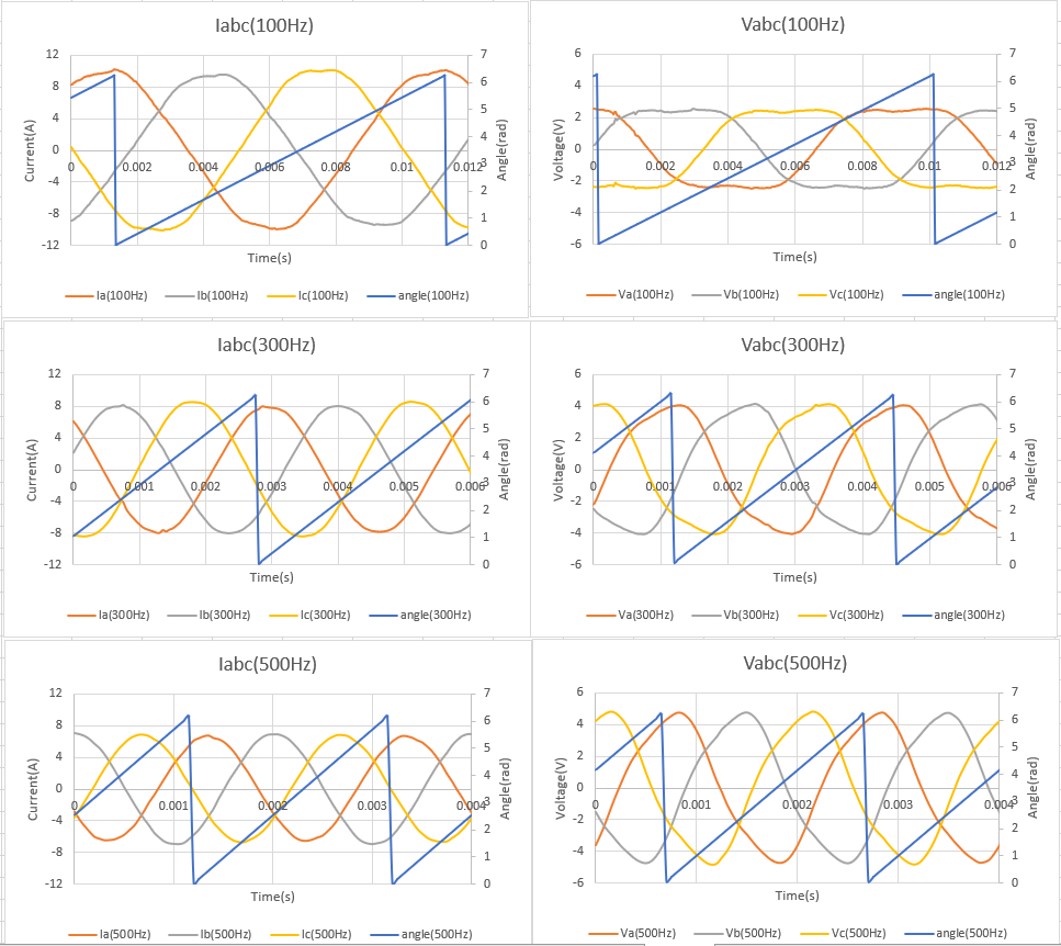
1. I setup and captured 256 samples (20kHz, 1 sample per ISR call) of angle, Vabc, and Iabc for 3 different speed references (100Hz, 300Hz, and 500Hz).  Basically i wanted to make sure the analog inputs were working as expected.  Plots of the signals are shown below:

OK.  Now the questions:

1. Why is the current so high?  And why does it go down as speed increases?  This seems odd to me.

2. I look at the current wave forms and conclude the analog current signals are being sampled without issue.  Do you see the same?

3. The 100Hz Vabc wave forms look ok in that they have the 3rd harmonic but the 300Hz and 500Hz dont seem to show the 3rd harmonic.  Is this normal?  Do this indicate there is an issue?

Thanks for your help!

Brett

  • Hi Brett,

    1. As the description of is03 in the lab guide, the is03 lab is a v/f control without using current and voltage sensing signals for current and position close loop. The v/f profile is not a linear curve as Figure 27 with adding a voltage compensation value at a low speed. So the phase current is not proportional to the running frequency. You might change the v/f profile to get better performance though this lab is just for hardware verification.

    #define USER_MOTOR_FREQ_LOW_HZ (20.0) // Hz
    #define USER_MOTOR_FREQ_HIGH_HZ (400.0) // Hz
    #define USER_MOTOR_VOLT_MIN_V (4.0) // Volt
    #define USER_MOTOR_VOLT_MAX_V (24.0) // Volt

    2. Yes, it's a normal appearance. As mentioned above, the output voltage only depends on the inverter and the v/f profile if you set the correct dead time for the gate drivers and power FET.

  • Mr Luo - the point of this post was to confirm the analog input signals (specifically, Iabc and Vabc) were sampled correctly and no anomalies were detected  even when run at speeds above 400Hz.  Do you agree that they are OK? or am i missing something?

    Brett

  • Yes, the feedback current looks good, but the phase voltage looks haveing a distortion at high speed, such as 300Hz, and 500Hz. Maybe, the reason is from the v/f control that is not fir for high speed over the rated frequency of the motor. If not, that means the filter pole frequency is too low on the hardware board.

  • Hey Mr Luo - thank you. 

    1. Since this is the TI dev board (LAUNCHXL F280049C) and inverter (BOOSTXL DRV8320RS) i am unsure of what you are saying.

    2. Are you saying the voltage filter cutoff frequency is dependent on the blower?  How so?

    3. I want to close this thread and go back to the FAST estimator thread.

    e2e.ti.com/.../921747

    Brett