This thread has been locked.

If you have a related question, please click the "Ask a related question" button in the top right corner. The newly created question will be automatically linked to this question.

TMS320F280049C: ePWM Global Load problem with SOC EPWM_setADCTriggerEventPrescale

Part Number: TMS320F280049C


Hi,

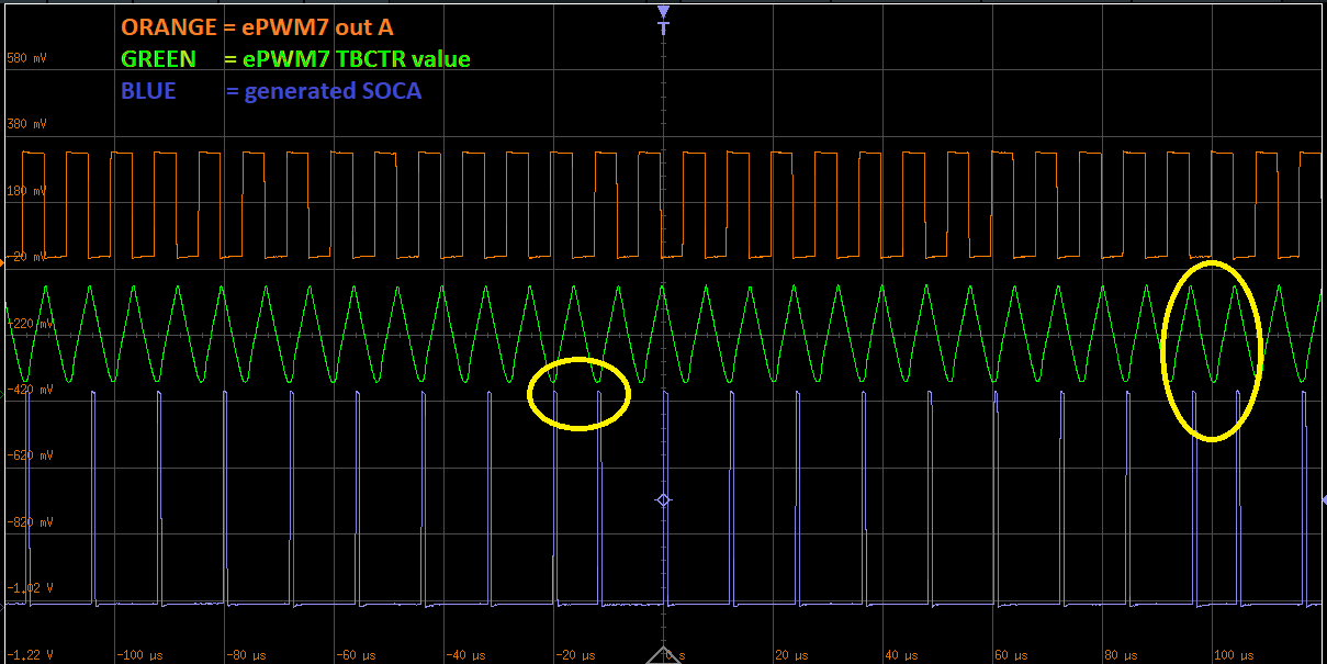
I am using PWM7 to generate SOC every 3rd time when TBCTR == ZERO or PRD. I change TBPRD value in interrupt from 400 to 401 . If I do not use global load everything works as expected. However If I also use global load in oneshot mode to load TBPRD value from shadow to active at TBCTR == PRD then the problem occurs. (Moreover It does not occur if shadow to active goes in TBCTR == ZERO).

The problem is that the SOC is every 3rd event, but sporadically it is every 2nd event. (Same if it is every 7th event, it sporadically happens every 6th event)

Here it is how it looks like:

Why this happens?

  • The circled pulses are when the global load is triggered?

  • I change period 

    EPwm7Regs.TBPRD = bSwitch ? 400 : 401; // change period

    and trigger the oneshot load for next TBCTR = PRD within the interrupt

    EPwm7Regs.GLDCTL2.bit.OSHTLD = 1; // FORCE ONE SHOT LOAD for period

    both within the ADC SOC interrupt which is marked with blue signal in the oscilloscope printscreen above.

  • I trigger global load each time at SOC. Cycled pulses occurs sporadically.

    Can you reproduce it? Shall I share a source code with you?

  • You change the PERIOD ON EVERY THIRD (every SOC)?

    At some point SOC gets generated on CTR=PRD, then you change the PRD to PRD + 1 then the CTR keeps counting up, and hits CTR= NEW PERIOD.

    An extra event is detected. This is a race condition issue. make sure you change your preiodat a suitable time, not a time that is too close to your events in this specific case.

    Nima

  • I don't think this is race condition issue.

    If CTR=PRD triggers SOC and then CPU is interrupted at EOC that is the time when I set PRD+1 into shadow register and require global load to do one shot load when CTR = ZERO. 

    I am attaching the source code. Please try to reproduce the problem and let me know what you think that could be the problem.

    #include "F28x_Project.h"
    #include "f28004x_device.h"
    #include "driverlib.h"
    #include "device.h"
    #include "string.h"
    #include "math.h"
    
    __attribute__((interrupt)) void ADC_EOC_interrupt ( void )
    {
        static bool bSwitch = true;
    
        EPwm5Regs.AQCSFRC.all = 2;                              // DEBUG PIN forces continuous high on output epwm5 B
    
        AdcaRegs.ADCINTFLGCLR.all = 1;                          // ACK INTERRUPT
        PieCtrlRegs.PIEACK.all = PIEACK_GROUP1;
    
        Interrupt_clearACKGroup(INTERRUPT_ACK_GROUP1);      // Must acknowledge the PIE group
        ADC_clearInterruptStatus(ADCA_BASE, ADC_INT_NUMBER1);   // Clear ADCINT1 flag
    
        EPwm7Regs.TBPRD = bSwitch ? 400 : 401;                  // change period
        bSwitch = !bSwitch;
    
        EPwm7Regs.GLDCTL2.bit.OSHTLD = 1;                       // FORCE ONE SHOT LOAD for period
    
        EPwm5Regs.AQCSFRC.all = 1;                              // DEBUG PIN forces continuous low on output epwm5 B
    }
    
    
    #define SYNCED_REGS             ((uint16_t)(EPWM_GL_REGISTER_TBPRD_TBPRDHR | EPWM_GL_REGISTER_CMPA_CMPAHR | EPWM_GL_REGISTER_CMPB_CMPBHR | EPWM_GL_REGISTER_CMPC | EPWM_GL_REGISTER_CMPD | EPWM_GL_REGISTER_DBRED_DBREDHR | EPWM_GL_REGISTER_DBFED_DBFEDHR | EPWM_GL_REGISTER_AQCSFRC))
    
    void PWM_Init(void)
    {
        SysCtl_disablePeripheral(SYSCTL_PERIPH_CLK_TBCLKSYNC);
    
        SysCtl_resetPeripheral(SYSCTL_PERIPH_RES_EPWM7);
        HRPWM_setTimeBaseCounterMode(EPWM7_BASE, EPWM_COUNTER_MODE_STOP_FREEZE);
        HRPWM_setClockPrescaler(EPWM7_BASE, EPWM_CLOCK_DIVIDER_1, EPWM_HSCLOCK_DIVIDER_1);
        HRPWM_setEmulationMode(EPWM7_BASE, EPWM_EMULATION_FREE_RUN);
        HRPWM_setTimeBaseCounterMode(EPWM7_BASE, EPWM_COUNTER_MODE_UP_DOWN);
    
        HRPWM_setTimeBaseCounter(EPWM7_BASE, 0UL);
        HRPWM_setTimeBasePeriod(EPWM7_BASE, 105250);
        HRPWM_setCountModeAfterSync(EPWM7_BASE, EPWM_COUNT_MODE_UP_AFTER_SYNC);
    
        // HR PWM
        HRPWM_enablePeriodControl(EPWM7_BASE);
        HRPWM_selectPeriodLoadEvent(EPWM7_BASE, EPWM_SHADOW_LOAD_MODE_COUNTER_ZERO);
    
        HRPWM_setCounterCompareValue(EPWM7_BASE, HRPWM_COUNTER_COMPARE_A, 0U);
        HRPWM_setCounterCompareValue(EPWM7_BASE, HRPWM_COUNTER_COMPARE_B, 0U);
        HRPWM_setActionQualifierAction(EPWM7_BASE, EPWM_AQ_OUTPUT_A, EPWM_AQ_OUTPUT_HIGH, EPWM_AQ_OUTPUT_ON_TIMEBASE_ZERO);
        HRPWM_setActionQualifierAction(EPWM7_BASE, EPWM_AQ_OUTPUT_A, EPWM_AQ_OUTPUT_LOW,  EPWM_AQ_OUTPUT_ON_TIMEBASE_PERIOD);
        HRPWM_setActionQualifierAction(EPWM7_BASE, EPWM_AQ_OUTPUT_B, EPWM_AQ_OUTPUT_LOW,  EPWM_AQ_OUTPUT_ON_TIMEBASE_PERIOD);
        HRPWM_setActionQualifierAction(EPWM7_BASE, EPWM_AQ_OUTPUT_B, EPWM_AQ_OUTPUT_HIGH, EPWM_AQ_OUTPUT_ON_TIMEBASE_ZERO);
    
        HRPWM_enableADCTrigger(EPWM7_BASE, EPWM_SOC_A);
        HRPWM_setADCTriggerEventPrescale(EPWM7_BASE, EPWM_SOC_A, 3);
        HRPWM_setADCTriggerSource(EPWM7_BASE, EPWM_SOC_A, EPWM_SOC_TBCTR_ZERO_OR_PERIOD);
        HRPWM_setADCTriggerEventCountInitValue(EPWM7_BASE, EPWM_SOC_A, 0 );
        HRPWM_disableADCTriggerEventCountInit(EPWM7_BASE, EPWM_SOC_A);
        HRPWM_forceADCTriggerEventCountInit(EPWM7_BASE, EPWM_SOC_A);
    
        // GLOBAL LOAD
        if (true)                                                                      // IF YOU DISABLE GLOBAL LOAD, IT WORKS CORRECTLY
        {
            HRPWM_enableGlobalLoad(EPWM7_BASE);
            HRPWM_enableGlobalLoadOneShotMode(EPWM7_BASE);
            HRPWM_enableGlobalLoadRegisters(EPWM7_BASE, SYNCED_REGS);
            HRPWM_setGlobalLoadTrigger(EPWM7_BASE, EPWM_GL_LOAD_PULSE_CNTR_PERIOD);
    
            EPwm7Regs.GLDCTL2.bit.OSHTLD = 1; // load shadow to active now
        }
    
        GPIO_setPadConfig(12, GPIO_PIN_TYPE_STD);
        GPIO_setDirectionMode(12, GPIO_DIR_MODE_OUT);
        GPIO_setPinConfig(GPIO_12_EPWM7A);
    
        GPIO_setPadConfig(13, GPIO_PIN_TYPE_STD);
        GPIO_setDirectionMode(13, GPIO_DIR_MODE_OUT);
        GPIO_setPinConfig(GPIO_13_EPWM7B);
    
        SysCtl_enablePeripheral(SYSCTL_PERIPH_CLK_TBCLKSYNC);
    
    }
    
    // AS IN EXAMPLE LAB6
    void ADC_Init(void)
    {
        //--- Reset the ADC.  This is good programming practice.
            SysCtl_resetPeripheral(SYSCTL_PERIPH_RES_ADCA);     // Reset ADC
    
        //--- Configure the ADC-A base registers
            ADC_disableConverter(ADCA_BASE);                                    // Power down ADC for configuration
            ADC_setVREF(ADCA_BASE, ADC_REFERENCE_INTERNAL, ADC_REFERENCE_3_3V); // VREF internal 3.3V
            ADC_setPrescaler(ADCA_BASE, ADC_CLK_DIV_4_0);                       // ADC clock prescaler = CPUCLK/4
            ADC_setInterruptPulseMode(ADCA_BASE, ADC_PULSE_END_OF_CONV);        // INT pulse generation = end of conversion
    
        //--- SOC0 configuration - Trigger using ePWM2-ADCSOCA; Convert channel ADCINA0; Acquisition window = 8 cycles
            ADC_setupSOC(ADCA_BASE, ADC_SOC_NUMBER0, ADC_TRIGGER_EPWM7_SOCA, ADC_CH_ADCIN0, 8);
    
        //--- No ADC interrupt triggers SOC0 (TRIGSEL determined by SOC and not ADCINT1 or ADCINT2)
            ADC_setInterruptSOCTrigger(ADCA_BASE, ADC_SOC_NUMBER0, ADC_INT_SOC_TRIGGER_NONE);
    
            ADC_setSOCPriority(ADCA_BASE, ADC_PRI_ALL_ROUND_ROBIN);             // All SOCs handled in round-robin mode
    
        //--- ADCA1 interrupt configuration
            ADC_enableContinuousMode(ADCA_BASE, ADC_INT_NUMBER1);                       // Interrupt pulses regardless of flag state
            ADC_setInterruptSource(ADCA_BASE, ADC_INT_NUMBER1, ADC_SOC_NUMBER0);        // EOC0 triggers the interrupt
            ADC_enableInterrupt(ADCA_BASE, ADC_INT_NUMBER1);                            // Enable the interrupt in the ADC
    
        //--- Enable ADCA1 interrupt
            Interrupt_register(INT_ADCA1, &ADC_EOC_interrupt);    // Re-map ADCA1 interrupt signal to call the ISR function
            Interrupt_enable(INT_ADCA1);                 // Enable ADCA1 in PIE group 1 and enable INT1 in IER to enable PIE group 1
    
        //--- Finish up
            ADC_enableConverter(ADCA_BASE);             // Power up the ADC
            DEVICE_DELAY_US(1000);                      // Wait 1 ms after power-up before using the ADC
    }
    
    int16 main(void)
    {
        Device_init();
        InitCpuTimers();
        StartCpuTimer0();
        Interrupt_initModule();
        Interrupt_initVectorTable();
    
        PWM_Init();
        ADC_Init();
    
        // DEBUG PIN raised in INT
        GPIO_setPadConfig(8, GPIO_PIN_TYPE_STD);
        GPIO_setPinConfig(GPIO_8_EPWM5A);
        GPIO_writePin(8, 0);
    
        EINT;
        ERTM;
    
        while(1)
        {
            NOP;
        }
    }


    Thank you.

  • Can you try something for me? 

    Instead of changing from 400 to 401, can you try switching to 450 and see if the issue still exists?

    Nima

  • Yes, the problem still exists if you change any values. 

    Can you try something for me? Please use the source code I attached in previous message and try to reproduce it locally at your device. It has no hardware dependency. 

    I need you to confirm if this is a hardware bug in periphery or what is wrong. 

    I am waiting for too long for an answer. 

  • Yes, I can try this on my HW. Are you using Launchpad or Control card?

  • I am using Control Card

  • Juraj,

    I removed a couple of lines this is the final c code I am going to test. Does this replicate your issue?

    #include "F28x_Project.h"
    #include "f2837xd_device.h"
    #include "driverlib.h"
    #include "device.h"
    #include "string.h"
    #include "math.h"
    
    __attribute__((interrupt)) void ADC_EOC_interrupt ( void )
    {
        static bool bSwitch = true;
    
        EPwm5Regs.AQCSFRC.all = 2;                              // DEBUG PIN forces continuous high on output epwm5 B
    
        AdcaRegs.ADCINTFLGCLR.all = 1;                          // ACK INTERRUPT
        PieCtrlRegs.PIEACK.all = PIEACK_GROUP1;
    
        Interrupt_clearACKGroup(INTERRUPT_ACK_GROUP1);      // Must acknowledge the PIE group
        ADC_clearInterruptStatus(ADCA_BASE, ADC_INT_NUMBER1);   // Clear ADCINT1 flag
    
        EPwm7Regs.TBPRD = bSwitch ? 400 : 401;                  // change period
        bSwitch = !bSwitch;
    
        EPwm7Regs.GLDCTL2.bit.OSHTLD = 1;                       // FORCE ONE SHOT LOAD for period
    
        EPwm5Regs.AQCSFRC.all = 1;                              // DEBUG PIN forces continuous low on output epwm5 B
    }
    
    
    #define SYNCED_REGS             ((uint16_t)(EPWM_GL_REGISTER_TBPRD_TBPRDHR | EPWM_GL_REGISTER_CMPA_CMPAHR | EPWM_GL_REGISTER_CMPB_CMPBHR | EPWM_GL_REGISTER_CMPC | EPWM_GL_REGISTER_CMPD | EPWM_GL_REGISTER_DBRED_DBREDHR | EPWM_GL_REGISTER_DBFED_DBFEDHR | EPWM_GL_REGISTER_AQCSFRC))
    
    void PWM_Init(void)
    {
        SysCtl_disablePeripheral(SYSCTL_PERIPH_CLK_TBCLKSYNC);
    
        SysCtl_resetPeripheral(SYSCTL_PERIPH_RES_EPWM7);
        HRPWM_setTimeBaseCounterMode(EPWM7_BASE, EPWM_COUNTER_MODE_STOP_FREEZE);
        HRPWM_setClockPrescaler(EPWM7_BASE, EPWM_CLOCK_DIVIDER_1, EPWM_HSCLOCK_DIVIDER_1);
        HRPWM_setEmulationMode(EPWM7_BASE, EPWM_EMULATION_FREE_RUN);
        HRPWM_setTimeBaseCounterMode(EPWM7_BASE, EPWM_COUNTER_MODE_UP_DOWN);
    
        HRPWM_setTimeBaseCounter(EPWM7_BASE, 0UL);
        HRPWM_setTimeBasePeriod(EPWM7_BASE, 105250);
        HRPWM_setCountModeAfterSync(EPWM7_BASE, EPWM_COUNT_MODE_UP_AFTER_SYNC);
    
        // HR PWM
        HRPWM_enablePeriodControl(EPWM7_BASE);
        HRPWM_selectPeriodLoadEvent(EPWM7_BASE, EPWM_SHADOW_LOAD_MODE_COUNTER_ZERO);
    
        HRPWM_setCounterCompareValue(EPWM7_BASE, HRPWM_COUNTER_COMPARE_A, 0U);
        HRPWM_setCounterCompareValue(EPWM7_BASE, HRPWM_COUNTER_COMPARE_B, 0U);
        HRPWM_setActionQualifierAction(EPWM7_BASE, EPWM_AQ_OUTPUT_A, EPWM_AQ_OUTPUT_HIGH, EPWM_AQ_OUTPUT_ON_TIMEBASE_ZERO);
        HRPWM_setActionQualifierAction(EPWM7_BASE, EPWM_AQ_OUTPUT_A, EPWM_AQ_OUTPUT_LOW,  EPWM_AQ_OUTPUT_ON_TIMEBASE_PERIOD);
        HRPWM_setActionQualifierAction(EPWM7_BASE, EPWM_AQ_OUTPUT_B, EPWM_AQ_OUTPUT_LOW,  EPWM_AQ_OUTPUT_ON_TIMEBASE_PERIOD);
        HRPWM_setActionQualifierAction(EPWM7_BASE, EPWM_AQ_OUTPUT_B, EPWM_AQ_OUTPUT_HIGH, EPWM_AQ_OUTPUT_ON_TIMEBASE_ZERO);
    
        HRPWM_enableADCTrigger(EPWM7_BASE, EPWM_SOC_A);
        HRPWM_setADCTriggerEventPrescale(EPWM7_BASE, EPWM_SOC_A, 3);
        HRPWM_setADCTriggerSource(EPWM7_BASE, EPWM_SOC_A, EPWM_SOC_TBCTR_ZERO_OR_PERIOD);
        HRPWM_setADCTriggerEventCountInitValue(EPWM7_BASE, EPWM_SOC_A, 0 );
        HRPWM_disableADCTriggerEventCountInit(EPWM7_BASE, EPWM_SOC_A);
        HRPWM_forceADCTriggerEventCountInit(EPWM7_BASE, EPWM_SOC_A);
    
        // GLOBAL LOAD
        if (true)                                                                      // IF YOU DISABLE GLOBAL LOAD, IT WORKS CORRECTLY
        {
            HRPWM_enableGlobalLoad(EPWM7_BASE);
            HRPWM_enableGlobalLoadOneShotMode(EPWM7_BASE);
            HRPWM_enableGlobalLoadRegisters(EPWM7_BASE, SYNCED_REGS);
            HRPWM_setGlobalLoadTrigger(EPWM7_BASE, EPWM_GL_LOAD_PULSE_CNTR_PERIOD);
    
            EPwm7Regs.GLDCTL2.bit.OSHTLD = 1; // load shadow to active now
        }
    
        GPIO_setPadConfig(12, GPIO_PIN_TYPE_STD);
        GPIO_setDirectionMode(12, GPIO_DIR_MODE_OUT);
        GPIO_setPinConfig(GPIO_12_EPWM7A);
    
        GPIO_setPadConfig(13, GPIO_PIN_TYPE_STD);
        GPIO_setDirectionMode(13, GPIO_DIR_MODE_OUT);
        GPIO_setPinConfig(GPIO_13_EPWM7B);
    
        SysCtl_enablePeripheral(SYSCTL_PERIPH_CLK_TBCLKSYNC);
    
    }
    
    // AS IN EXAMPLE LAB6
    void ADC_Init(void)
    {
        //--- Reset the ADC.  This is good programming practice.
            SysCtl_resetPeripheral(SYSCTL_PERIPH_RES_ADCA);     // Reset ADC
    
        //--- Configure the ADC-A base registers
            ADC_disableConverter(ADCA_BASE);                                    // Power down ADC for configuration
    
            ADC_setPrescaler(ADCA_BASE, ADC_CLK_DIV_4_0);                       // ADC clock prescaler = CPUCLK/4
            ADC_setInterruptPulseMode(ADCA_BASE, ADC_PULSE_END_OF_CONV);        // INT pulse generation = end of conversion
    
        //--- SOC0 configuration - Trigger using ePWM2-ADCSOCA; Convert channel ADCINA0; Acquisition window = 8 cycles
            ADC_setupSOC(ADCA_BASE, ADC_SOC_NUMBER0, ADC_TRIGGER_EPWM7_SOCA, ADC_CH_ADCIN0, 8);
    
        //--- No ADC interrupt triggers SOC0 (TRIGSEL determined by SOC and not ADCINT1 or ADCINT2)
            ADC_setInterruptSOCTrigger(ADCA_BASE, ADC_SOC_NUMBER0, ADC_INT_SOC_TRIGGER_NONE);
    
            ADC_setSOCPriority(ADCA_BASE, ADC_PRI_ALL_ROUND_ROBIN);             // All SOCs handled in round-robin mode
    
        //--- ADCA1 interrupt configuration
            ADC_enableContinuousMode(ADCA_BASE, ADC_INT_NUMBER1);                       // Interrupt pulses regardless of flag state
            ADC_setInterruptSource(ADCA_BASE, ADC_INT_NUMBER1, ADC_SOC_NUMBER0);        // EOC0 triggers the interrupt
            ADC_enableInterrupt(ADCA_BASE, ADC_INT_NUMBER1);                            // Enable the interrupt in the ADC
    
        //--- Enable ADCA1 interrupt
            Interrupt_register(INT_ADCA1, &ADC_EOC_interrupt);    // Re-map ADCA1 interrupt signal to call the ISR function
            Interrupt_enable(INT_ADCA1);                 // Enable ADCA1 in PIE group 1 and enable INT1 in IER to enable PIE group 1
    
        //--- Finish up
            ADC_enableConverter(ADCA_BASE);             // Power up the ADC
            DEVICE_DELAY_US(1000);                      // Wait 1 ms after power-up before using the ADC
    }
    
    int16 main(void)
    {
        Device_init();
        InitCpuTimers();
        StartCpuTimer0();
        Interrupt_initModule();
        Interrupt_initVectorTable();
    
        PWM_Init();
        ADC_Init();
    
        // DEBUG PIN raised in INT
        GPIO_setPadConfig(8, GPIO_PIN_TYPE_STD);
        GPIO_setPinConfig(GPIO_8_EPWM5A);
        GPIO_writePin(8, 0);
    
        EINT;
        ERTM;
    
        while(1)
        {
            NOP;
        }
    }


    Nima

  • Juraj,

    Please make sure to confirm that removing the line: 

    ADC_setVREF(ADCA_BASE, ADC_REFERENCE_INTERNAL, ADC_REFERENCE_3_3V); // VREF internal 3.3V

    Still causes the issue. I have to test this on an F2837xD control card and had to port your code over before I can test it.

    They have the same EPWM module so we should be able to test this scenario.

    Nima

  • Yes, it still reproduces my issue.

  • Okay I am running it on my setup, but unfortunately I dont see the closer pulses...

    Is there another way to detect this maybe? a timer to capture the closer pulses? Maybe my scope is not capturing enough pulses?

  • This code isn't changing the period at all.

    I tried changing the:

    EPwm7Regs.TBPRD = bSwitch ? 5000 : 5001;  

    And it doesn't change the distance between the pulses. Meaning the new PRD value is being written to the register but the new PRD is not being shadow loaded.

    Nima

  • You have global load mode left ON...

    You must turn this off for shadow loading on CTR=ZERO to happen again.


    HRPWM_disableGlobalLoad(EPWM7_BASE);

  • I recommend, to improve this debug experience, please remove ADC, use EPWM interrupt, then instead of trying to catch the error on oscilloscope, lets set up a timer and detect an error when the delay between the interrupts is not the same as expected.

    Currently I have a hard time recreating this for you. 

    With the original code you sent, the PRD is not even loaded with the new value in the ISR.

    Nima

  • Juraj,

    Were you able to look at my results?

    If you can send me an ePWM only code where the issue occurs, I can test again on my device.

    Nima

  • Hi,

    You have the source code where the issue occurs. The problem is generating of SOC for ADC so I cannot do it without ADC module.

  • Juraj,

    Can you modify the code you send me to have CPU TIMER, which counts the number of cycles between ISRs, and when the ISRs are too close, we can set a GPIO high?

    This way maybe we can definitively catch it on the scope? Currently with the version of the code I have, I am not able to replicate this.

    Nima

  • Juraj,

    Were you able to add in the CPU TIMER so we can catch the anomaly in SW?

    Nima

  • I was not able to add CPU timer. Could you please try to add CPU timer?

  • Juraj,

    Please review this example of the CPUTIMER, and add a code that counts the number of cycles between TWO interrupts. then add an if statement in the Interrupt for when the COUNT is too low.

    Nima

  • //#############################################################################
    //
    // FILE:   timer_ex1_cputimers.c
    //
    // TITLE:  CPU Timers Example
    //
    //! \addtogroup driver_example_list
    //! <h1> CPU Timers </h1>
    //!
    //! This example configures CPU Timer0, 1, and 2 and increments
    //! a counter each time the timer asserts an interrupt.
    //!
    //! \b External \b Connections \n
    //!  - None
    //!
    //! \b Watch \b Variables \n
    //! - cpuTimer0IntCount
    //! - cpuTimer1IntCount
    //! - cpuTimer2IntCount
    //!
    //
    //#############################################################################
    // $TI Release: F28004x Support Library v1.10.00.00 $
    // $Release Date: Tue May 26 17:06:03 IST 2020 $
    // $Copyright:
    // Copyright (C) 2020 Texas Instruments Incorporated - http://www.ti.com/
    //
    // Redistribution and use in source and binary forms, with or without 
    // modification, are permitted provided that the following conditions 
    // are met:
    // 
    //   Redistributions of source code must retain the above copyright 
    //   notice, this list of conditions and the following disclaimer.
    // 
    //   Redistributions in binary form must reproduce the above copyright
    //   notice, this list of conditions and the following disclaimer in the 
    //   documentation and/or other materials provided with the   
    //   distribution.
    // 
    //   Neither the name of Texas Instruments Incorporated nor the names of
    //   its contributors may be used to endorse or promote products derived
    //   from this software without specific prior written permission.
    // 
    // THIS SOFTWARE IS PROVIDED BY THE COPYRIGHT HOLDERS AND CONTRIBUTORS 
    // "AS IS" AND ANY EXPRESS OR IMPLIED WARRANTIES, INCLUDING, BUT NOT 
    // LIMITED TO, THE IMPLIED WARRANTIES OF MERCHANTABILITY AND FITNESS FOR
    // A PARTICULAR PURPOSE ARE DISCLAIMED. IN NO EVENT SHALL THE COPYRIGHT 
    // OWNER OR CONTRIBUTORS BE LIABLE FOR ANY DIRECT, INDIRECT, INCIDENTAL, 
    // SPECIAL, EXEMPLARY, OR CONSEQUENTIAL DAMAGES (INCLUDING, BUT NOT 
    // LIMITED TO, PROCUREMENT OF SUBSTITUTE GOODS OR SERVICES; LOSS OF USE,
    // DATA, OR PROFITS; OR BUSINESS INTERRUPTION) HOWEVER CAUSED AND ON ANY
    // THEORY OF LIABILITY, WHETHER IN CONTRACT, STRICT LIABILITY, OR TORT 
    // (INCLUDING NEGLIGENCE OR OTHERWISE) ARISING IN ANY WAY OUT OF THE USE 
    // OF THIS SOFTWARE, EVEN IF ADVISED OF THE POSSIBILITY OF SUCH DAMAGE.
    // $
    //#############################################################################
    
    //
    // Included Files
    //
    #include "driverlib.h"
    #include "device.h"
    
    //
    // Globals
    //
    uint16_t cpuTimer0IntCount;
    uint16_t cpuTimer1IntCount;
    uint16_t cpuTimer2IntCount;
    
    //
    // Function Prototypes
    //
    __interrupt void cpuTimer0ISR(void);
    __interrupt void cpuTimer1ISR(void);
    __interrupt void cpuTimer2ISR(void);
    void initCPUTimers(void);
    void configCPUTimer(uint32_t, float, float);
    
    //
    // Main
    //
    void main(void)
    {
        //
        // Initializes device clock and peripherals
        //
        Device_init();
    
        //
        // Configures the GPIO pin as a push-pull output
        //
        Device_initGPIO();
        GPIO_setPinConfig(DEVICE_GPIO_CFG_LED1);
        GPIO_setMasterCore(DEVICE_GPIO_PIN_LED1, GPIO_CORE_CPU1);
        GPIO_setPadConfig(DEVICE_GPIO_PIN_LED1, GPIO_PIN_TYPE_STD);
        GPIO_setDirectionMode(DEVICE_GPIO_PIN_LED1, GPIO_DIR_MODE_OUT);
    
        //
        // Initializes PIE and clears PIE registers. Disables CPU interrupts.
        //
        Interrupt_initModule();
    
        //
        // Initializes the PIE vector table with pointers to the shell Interrupt
        // Service Routines (ISR).
        //
        Interrupt_initVectorTable();
    
        //
        // ISRs for each CPU Timer interrupt
        //
        Interrupt_register(INT_TIMER0, &cpuTimer0ISR);
        Interrupt_register(INT_TIMER1, &cpuTimer1ISR);
        Interrupt_register(INT_TIMER2, &cpuTimer2ISR);
    
        //
        // Initializes the Device Peripheral. For this example, only initialize the
        // Cpu Timers.
        //
        initCPUTimers();
    
        //
        // Configure CPU-Timer 0, 1, and 2 to interrupt every second:
        // 1 second Period (in uSeconds)
        //
        configCPUTimer(CPUTIMER0_BASE, DEVICE_SYSCLK_FREQ, 1000000);
        configCPUTimer(CPUTIMER1_BASE, DEVICE_SYSCLK_FREQ, 1000000);
        configCPUTimer(CPUTIMER2_BASE, DEVICE_SYSCLK_FREQ, 1000000);
    
        //
        // To ensure precise timing, use write-only instructions to write to the
        // entire register. Therefore, if any of the configuration bits are changed
        // in configCPUTimer and initCPUTimers, the below settings must also
        // be updated.
        //
        CPUTimer_enableInterrupt(CPUTIMER0_BASE);
        CPUTimer_enableInterrupt(CPUTIMER1_BASE);
        CPUTimer_enableInterrupt(CPUTIMER2_BASE);
    
        //
        // Enables CPU int1, int13, and int14 which are connected to CPU-Timer 0,
        // CPU-Timer 1, and CPU-Timer 2 respectively.
        // Enable TINT0 in the PIE: Group 1 interrupt 7
        //
        Interrupt_enable(INT_TIMER0);
        Interrupt_enable(INT_TIMER1);
        Interrupt_enable(INT_TIMER2);
    
        //
        // Starts CPU-Timer 0, CPU-Timer 1, and CPU-Timer 2.
        //
        CPUTimer_startTimer(CPUTIMER0_BASE);
        CPUTimer_startTimer(CPUTIMER1_BASE);
        CPUTimer_startTimer(CPUTIMER2_BASE);
    
        //
        // Enable Global Interrupt (INTM) and realtime interrupt (DBGM)
        //
        EINT;
        ERTM;
    
        //
        // IDLE loop. Just sit and loop forever (optional)
        //
        while(1)
        {
        }
    }
    
    //
    // initCPUTimers - This function initializes all three CPU timers
    // to a known state.
    //
    void
    initCPUTimers(void)
    {
        //
        // Initialize timer period to maximum
        //
        CPUTimer_setPeriod(CPUTIMER0_BASE, 0xFFFFFFFF);
        CPUTimer_setPeriod(CPUTIMER1_BASE, 0xFFFFFFFF);
        CPUTimer_setPeriod(CPUTIMER2_BASE, 0xFFFFFFFF);
    
        //
        // Initialize pre-scale counter to divide by 1 (SYSCLKOUT)
        //
        CPUTimer_setPreScaler(CPUTIMER0_BASE, 0);
        CPUTimer_setPreScaler(CPUTIMER1_BASE, 0);
        CPUTimer_setPreScaler(CPUTIMER2_BASE, 0);
    
        //
        // Make sure timer is stopped
        //
        CPUTimer_stopTimer(CPUTIMER0_BASE);
        CPUTimer_stopTimer(CPUTIMER1_BASE);
        CPUTimer_stopTimer(CPUTIMER2_BASE);
    
        //
        // Reload all counter register with period value
        //
        CPUTimer_reloadTimerCounter(CPUTIMER0_BASE);
        CPUTimer_reloadTimerCounter(CPUTIMER1_BASE);
        CPUTimer_reloadTimerCounter(CPUTIMER2_BASE);
    
        //
        // Reset interrupt counter
        //
        cpuTimer0IntCount = 0;
        cpuTimer1IntCount = 0;
        cpuTimer2IntCount = 0;
    }
    
    //
    // configCPUTimer - This function initializes the selected timer to the
    // period specified by the "freq" and "period" parameters. The "freq" is
    // entered as Hz and the period in uSeconds. The timer is held in the stopped
    // state after configuration.
    //
    void
    configCPUTimer(uint32_t cpuTimer, float freq, float period)
    {
        uint32_t temp;
    
        //
        // Initialize timer period:
        //
        temp = (uint32_t)(freq / 1000000 * period);
        CPUTimer_setPeriod(cpuTimer, temp);
    
        //
        // Set pre-scale counter to divide by 1 (SYSCLKOUT):
        //
        CPUTimer_setPreScaler(cpuTimer, 0);
    
        //
        // Initializes timer control register. The timer is stopped, reloaded,
        // free run disabled, and interrupt enabled.
        // Additionally, the free and soft bits are set
        //
        CPUTimer_stopTimer(cpuTimer);
        CPUTimer_reloadTimerCounter(cpuTimer);
        CPUTimer_setEmulationMode(cpuTimer,
                                  CPUTIMER_EMULATIONMODE_STOPAFTERNEXTDECREMENT);
        CPUTimer_enableInterrupt(cpuTimer);
    
        //
        // Resets interrupt counters for the three cpuTimers
        //
        if (cpuTimer == CPUTIMER0_BASE)
        {
            cpuTimer0IntCount = 0;
        }
        else if(cpuTimer == CPUTIMER1_BASE)
        {
            cpuTimer1IntCount = 0;
        }
        else if(cpuTimer == CPUTIMER2_BASE)
        {
            cpuTimer2IntCount = 0;
        }
    }
    
    //
    // cpuTimer0ISR - Counter for CpuTimer0
    //
    __interrupt void
    cpuTimer0ISR(void)
    {
        cpuTimer0IntCount++;
    
        //
        // Acknowledge this interrupt to receive more interrupts from group 1
        //
        Interrupt_clearACKGroup(INTERRUPT_ACK_GROUP1);
    }
    
    //
    // cpuTimer1ISR - Counter for CpuTimer1
    //
    __interrupt void
    cpuTimer1ISR(void)
    {
        //
        // The CPU acknowledges the interrupt.
        //
        cpuTimer1IntCount++;
    }
    
    //
    // cpuTimer2ISR - Counter for CpuTimer2
    //
    __interrupt void
    cpuTimer2ISR(void)
    {
        //
        // The CPU acknowledges the interrupt.
        //
        cpuTimer2IntCount++;
    }
    
    //
    // End of File
    //
    

  • Juraj,

    Did you have a chance to add the CPU TIMER code? And catch the anamoly situation?

    Nima

  • Hi, sorry I am busy, I had no time. Did you have time to try it?

  • No please let me know once you have it ready and I can test again to see if it reproduces on my end.