Hello,
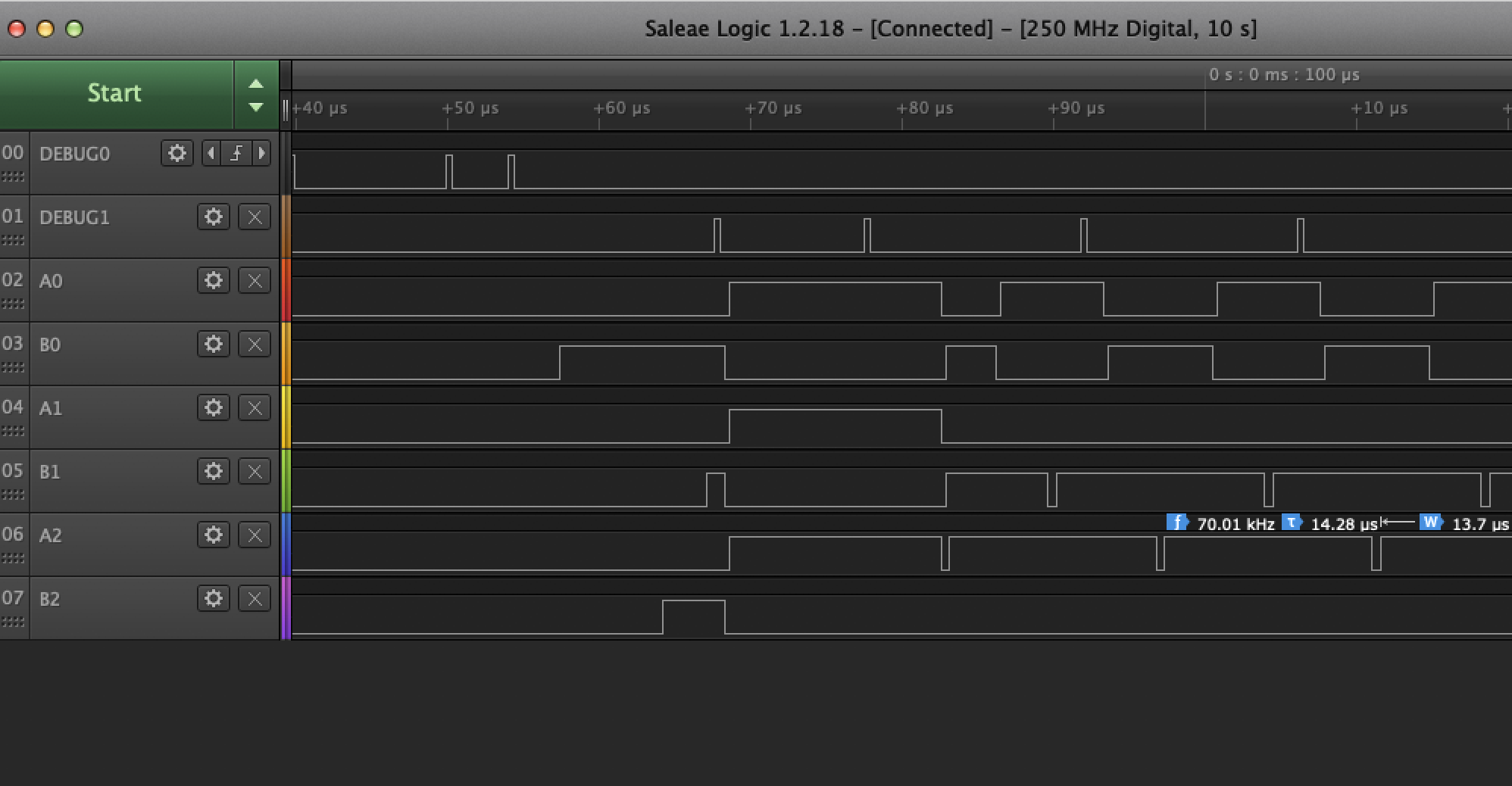
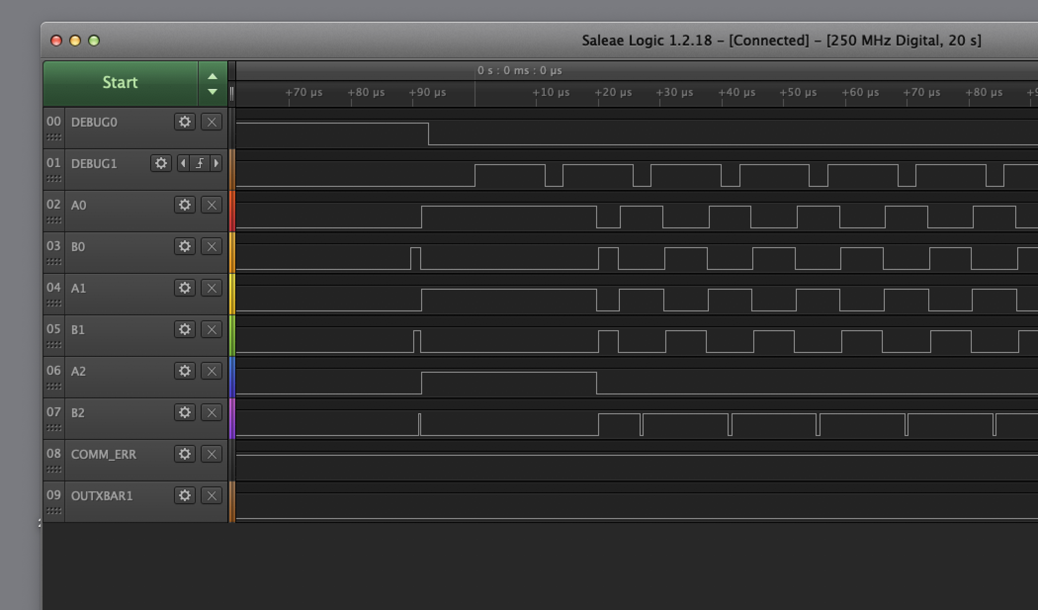
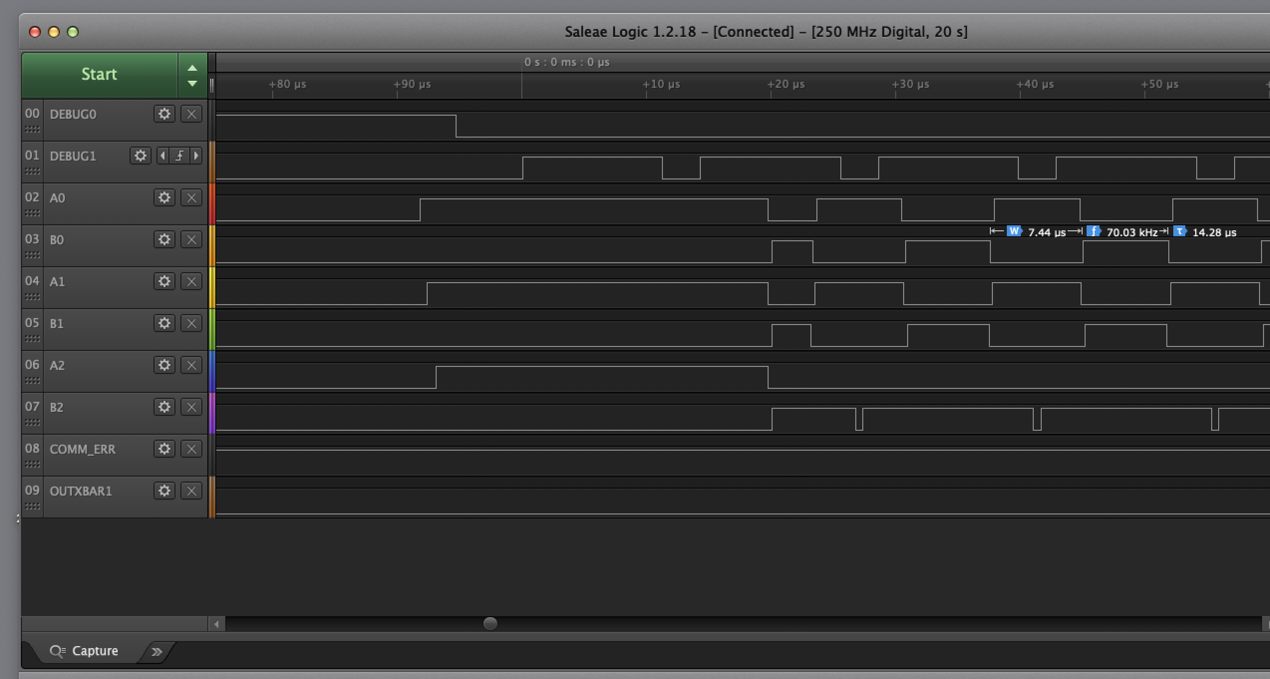
in the corse of initiating 3 PWMs, I always end up with a signal pattern, that I do not expect. I really appreciate the quality of the reference manual. It's very well written and easy to comprehend. I probably missed something, I did not managed to set the PWM up, so that both A and B stay at low and to have a duty cycle of 0% for the first PWM period (it seems to be close to 100%).
I've initialized the PWM Time Base as Up/Down counter. I configured output A to reset when TBCTR = 0, to switch to high, when TBCTR = CMPA on up counting and to go back to low when TBCTR = CMPB. That work very well. I generate a complementary output B, by configuring the dead band module to generate a RED and FED and to set B to be inverted from A. That works very well too.
But: As soon as I configure the dead band module, the B outputs go to high. I've mitigate that by, forcing a CBC trip zone event, that sets the outputs to low and get reseted at the end of the first period. That reduces the time, the complementary outputs are high to a few ~10ns (one period of the PWMCLK). Is there a way to use the dead band module to generate a complementary output, without setting the B output to 1 immediately or to get rid of the 10ns glitch? (maybe reseting the CBC event at the beginning of the period, not the end)
The "trick" with the trip zone event also has the nice side effect, that the output stay low during the first period.
best regards,
Torsten Robitzki