Hi Expert,
F280049 is used in customer new project. Customer meet a question about triangle signal trigger and output. Could you help us on that? I'll appreciate it if you can help. Thanks.
Here is the background and issue description:
Pin Configuration: Input Pin: Pin10(A3), Output Pin: Pin79(GPIO0);
Input signal: Triangle wave, 50~300KHz
Target output Signal: Output frequency follow input signal, output pulse width is fixed to 3.5uS
Configuration flow: CMPSSx -> DCEVT -> ePWM, output high start from the zero point of triangle wave
Issue description:
- Abnormal scenario: When the input signal frequency change from 50kHz, output ePWM is lost, or the pulse width is not correct;
- Normal scenario: When input signal frequency higher than 270kHz, output ePWM is always high.
- Change the triangle wave to pulse wave, the output frequency follow input frequency, but the pulse width is not correct
Firmware setting:
See the attachment for detail.
-------------------cmpss configuration code------------------------------------
EALLOW;
//  signal generator--->ADC_A3(pin10)--->CMP1HP
AnalogSubsysRegs.CMPHPMXSEL.bit.CMP1HPMXSEL = 3;
// Disable CMPSS1
Cmpss1Regs.COMPCTL.bit.COMPDACE = 0;

// NEG signal comes from DAC
Cmpss1Regs.COMPCTL.bit.COMPHSOURCE = NEGIN_DAC;

#if 0
// Configure CTRIPOUT path
Cmpss1Regs.COMPCTL.bit.CTRIPHSEL = CTRIP_FILTER; // ????and outpwm 50~300k ok, ?????outpwm???
Cmpss1Regs.COMPCTL.bit.CTRIPOUTHSEL = CTRIP_FILTER;
//Cmpss1Regs.COMPCTL.bit.CTRIPHSEL = CTRIP_LATCH; // ??????? ????????
//Cmpss1Regs.COMPCTL.bit.CTRIPOUTHSEL = CTRIP_LATCH;
/* Maximum CLKPRESCALE value provides the most time between samples */
Cmpss1Regs.CTRIPHFILCLKCTL.bit.CLKPRESCALE = 0x1;
/* Set SAMPWIN and THRESH */
// Cmpss1Regs.CTRIPHFILCTL.bit.SAMPWIN = 6;
// Cmpss1Regs.CTRIPHFILCTL.bit.THRESH = 6;
Cmpss1Regs.CTRIPHFILCTL.bit.SAMPWIN = 1;
Cmpss1Regs.CTRIPHFILCTL.bit.THRESH = 1;
/* Reset filter logic & start filtering */
Cmpss1Regs.CTRIPHFILCTL.bit.FILINIT = 1;
#else
// Configure CTRIPOUT path
Cmpss1Regs.COMPCTL.bit.CTRIPHSEL = CTRIP_ASYNCH;
Cmpss1Regs.COMPCTL.bit.CTRIPOUTHSEL = CTRIP_ASYNCH;
// Cmpss1Regs.COMPCTL.bit.CTRIPHSEL = CTRIP_SYNCH;
// Cmpss1Regs.COMPCTL.bit.CTRIPOUTHSEL = CTRIP_SYNCH;
#endif
// Use VDDA as the reference for DAC
Cmpss1Regs.COMPDACCTL.bit.DACSOURCE = 0; // DACVALS
Cmpss1Regs.COMPDACCTL.bit.SWLOADSEL = 0; // SYSCLK
Cmpss1Regs.COMPDACCTL.bit.SELREF = REFERENCE_VDDA;
Cmpss1Regs.DACHVALS.bit.DACVAL = 500; // 1--->0 trip
//Cmpss1Regs.DACHVALS.bit.DACVAL = 10;
//Cmpss1Regs.DACHVALS.bit.DACVAL = 2048;

// Enable CMPSS1
Cmpss1Regs.COMPCTL.bit.COMPDACE = 1; // ADC_A3(pin10)<----PWM/DG4062
EDIS;
-------------------pwm configuration code------------------------------------
EPwm1Regs.TBCTR = 0; // Clear counter
EPwm1Regs.TBPHS.bit.TBPHS = 0; // Set as master, phase =0
EPwm1Regs.TBPRD = DC_DC_FREQUENCY_Khz(20); // 5000

EPwm1Regs.TBCTL.bit.PHSEN = TB_ENABLE;
EPwm1Regs.TBCTL.bit.SYNCOSEL = TB_SYNC_IN;
EPwm1Regs.TBCTL.bit.PHSDIR = TB_UP; // Phase Direction Down
EPwm1Regs.TBCTL.bit.CTRMODE = TB_COUNT_UP; // Count up
EPwm1Regs.TBCTL.bit.PRDLD = TB_SHADOW;
EPwm1Regs.TBCTL.bit.CLKDIV = TB_DIV1; // Timebase clock pre-scale
EPwm1Regs.TBCTL.bit.HSPCLKDIV = TB_DIV1; // High speed time pre-scale
EPwm1Regs.CMPCTL.bit.LOADAMODE = CC_CTR_ZERO;
EPwm1Regs.CMPCTL.bit.LOADBMODE = CC_CTR_ZERO;
EPwm1Regs.CMPCTL.bit.SHDWAMODE = CC_SHADOW;
EPwm1Regs.CMPCTL.bit.SHDWBMODE = CC_SHADOW;
EPwm1Regs.AQCTLA.bit.ZRO = AQ_SET;
EPwm1Regs.AQCTLA.bit.CAU = AQ_CLEAR;
EPwm1Regs.AQCTLB.bit.ZRO = AQ_SET;
EPwm1Regs.AQCTLB.bit.CAU = AQ_CLEAR;
EPwm1Regs.DBCTL.bit.IN_MODE = DBA_RED_DBB_FED; // IN_mode selection, A->rising B->falling
EPwm1Regs.DBCTL.bit.POLSEL = DB_ACTV_HIC; // PWMxB inverted
EPwm1Regs.DBCTL.bit.OUT_MODE = 0x3;
EPwm1Regs.DBRED.bit.DBRED = DB_NS_300;//DEAD_TIME;
EPwm1Regs.DBFED.bit.DBFED = DB_NS_300;//DEAD_TIME;
----------------------xbar and DCEVT configuration code------------------------------------------------------------------
// ADC_A3(pin10)--->CMPSS1.CTRIPH--->TRIP4
EPwmXbarRegs.TRIP4MUX0TO15CFG.bit.MUX0 = 0;
EPwmXbarRegs.TRIP4MUXENABLE.bit.MUX0 = 1;

// TRIP4-->DCAH
EPwm1Regs.DCTRIPSEL.bit.DCAHCOMPSEL = DC_TRIPIN4; // single
EPwm1Regs.DCAHTRIPSEL.bit.TRIPINPUT4 = 1; // multiply

// DCAH-->DCAEVT2
EPwm1Regs.TZDCSEL.bit.DCAEVT1 = TZ_DCAH_HI; // DCAH = low, DCAL = don't care // 0---->1
EPwm1Regs.DCACTL.bit.EVT1SRCSEL = DC_EVT2; // DCAEVT2 = DCAEVT2 (not filtered)
EPwm1Regs.DCACTL.bit.EVT1FRCSYNCSEL = DC_EVT_ASYNC; // Take async path
// EPwm1Regs.DCACTL.bit.EVT1FRCSYNCSEL = DC_EVT_SYNC;
EPwm1Regs.DCACTL.bit.EVT1SYNCE = 1;
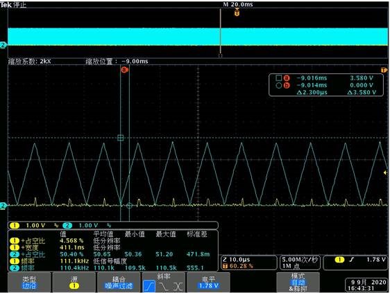
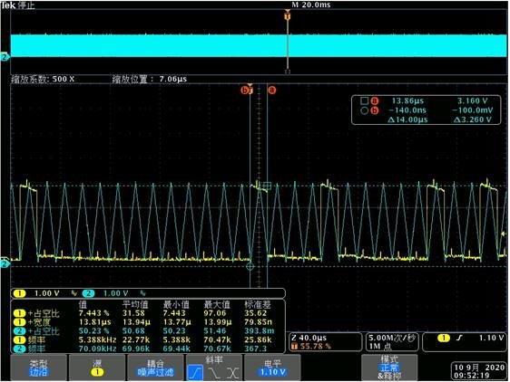
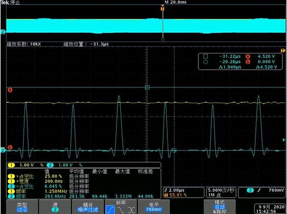
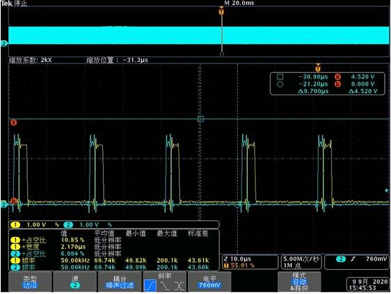
Waveform capture
Blue is for Pin10(input signal), Yellow is for Pin79(Output):
When the input signal frequency is 100.4kHz, output is lost
When the input signal frequency is 70.09kHz, output pulse width is not correct
When the frequency of input signal higher than 270kHz, output is keep high
Change the triangle wave to pulse wave, the frequency is correct, but the pulse width is not correct
Best Regards
Songzhen Guo


