Part Number: TMS320F28335
Iam trying to read the values of Hall sensor signals at pin no 24 25 26 using eCAP.But the GPADAT is not able to detect the change in Hall sensor signals at speeds above 10 RPM.
Thanks in advance
S. Chand
This thread has been locked.
If you have a related question, please click the "Ask a related question" button in the top right corner. The newly created question will be automatically linked to this question.
Part Number: TMS320F28335
Iam trying to read the values of Hall sensor signals at pin no 24 25 26 using eCAP.But the GPADAT is not able to detect the change in Hall sensor signals at speeds above 10 RPM.
Thanks in advance
S. Chand
Hi Chan,
I think you mean GPIO24,25 and 26, not pin number. Is it correct?
How often do you read GPADAT in your software? Have you checked if the hall pulse signals are input to MCU pins without any distortion at over 10 rpm?
Regards,
Steve
Hi Steve,
Thank you for your response.
Yes I meant GPIO 24 25 26.
I am actually using matlab simulink and Texas C2000 addons to build the code and build. So in the blocks I have set the sample time to -1. If u can guide me where exactly I should be checking to find out how often the signals are being sampled I will look into the C code which is generated after building the program. Yes the Hall signals are generated without any disturbance I have checked them on a DSO.
Best
S. Chand
S. Chand,
it sounds like you are trying to use two methods of reading the hall sensor at the same time
With method one all you need to do is configure the peripheral and then wait for it to report the values. This will work for very fast signals by comparison to your 10Hz signal.
With method two this is very software depended on how often you read your GPDAT register. If you read it slowly it will have poor resolution and possibly lose the hall information above a certain frequency. Even with poorly written code you should be able to get well above 10 Hz though, this device operates at 150MHz, which is clearly many orders of magnitude faster than your input signal
Regards,
Cody
Cody,
Thank you for the response.
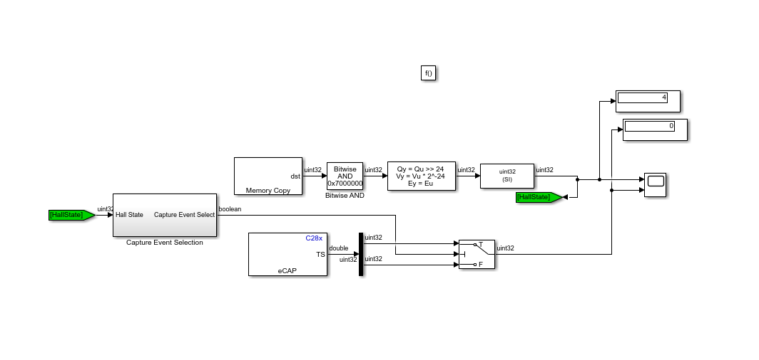
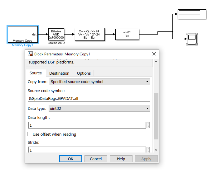
iam trying to find the speed using the below matlab simulink model I am reading the hall state using the first figure and the have written the logic in capture event select block such that if hall state is equal to 1or 5 then the capture event one will takes place else then capture event two will take place.finaly the time difference between them is measured and speed is calculated. When I am building only the first simulink model alone then it is able to detect the hall state at 10 rpm but and above its failing.But when iam building the second simulink model then hall state doesn't change at all.
Hi Saichand,
Please check-out our shipping example on the Hall sensor and eCAP.
c28069pmsmfoc_ert
This model should provide you good details.
Also encourage you to go through below documentation.
thank you for your reply MR.Venkatesh Chilapur.
I am actually using the same example which you mentioned but I made some modifications to the simulation like removed the serial communication and ADC interrupts cause I just wanted to check the functioning of eCAP modules when I am doing so the values of hall signals are changing properly from the sensors but the GPIO.DATA register is not able t track the changes(grey code 5 4 6 2 3 1)properly unless the rotor is rotated at very low speed like 10 rpm.
please help me with this sir.
thanks in advance
s.p.saichand
Saichand,
you shouldn't need to do a memcopy from the data register to determine the speed. Just use the output of the eCAP. The eCAP has configurable interrupts too which should help you calculate the result when ready. Using interrupts is far more efficient than polling a register and works for both low and high speeds.
Regards,
Cody