


Part Number: TMS320F28075
Hi,
my customer is using HRPWM to output a duty cycle PWM to drive the high side of a buck controller.
In theory the output current should be proportional to the duty cycle of the buck converter. So by looking at the current we could see the duty cycle of the PWM generated.
We can't use an scope to measure the duty cycle because the resolution is not enough to see such small change in duty cycle.
We get the result below:
| duty cycle expected | duty cycle increment | CMPA | CMPAHR | current measured | current expected | TBPRD |
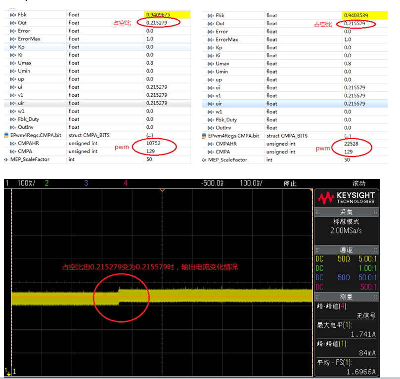
| 0.215279 | 129 | 10752 | 1 | 1 | 600 | |
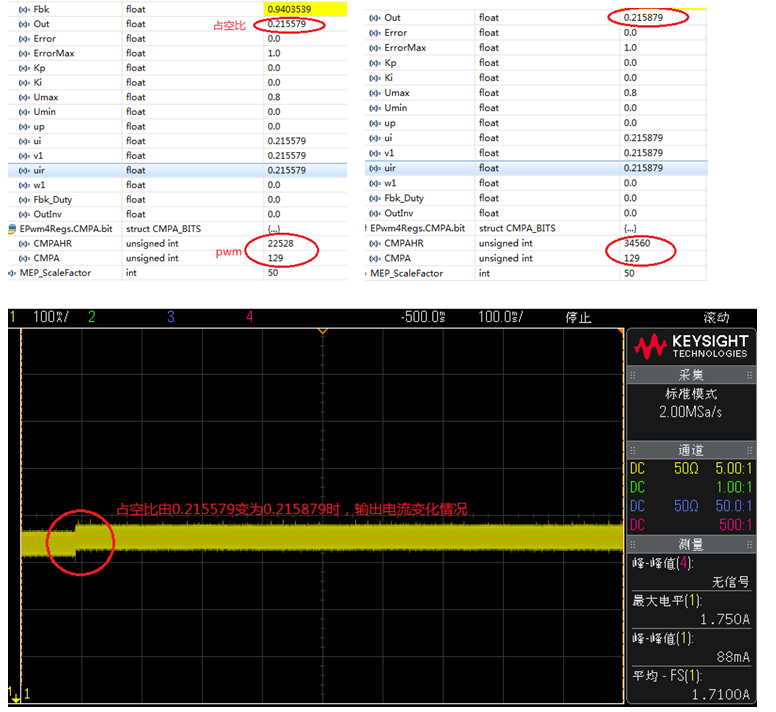
| 0.215579 | 0.003 | 129 | 22528 | 1.1 | 1.2 | 600 |
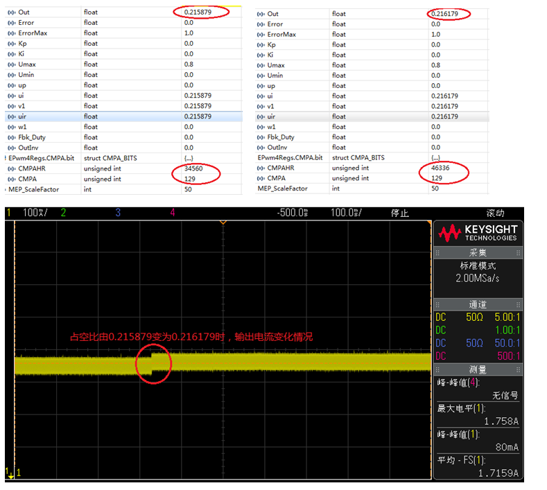
| 0.215879 | 0.003 | 129 | 34560 | 1.2 | 1.4 | 600 |
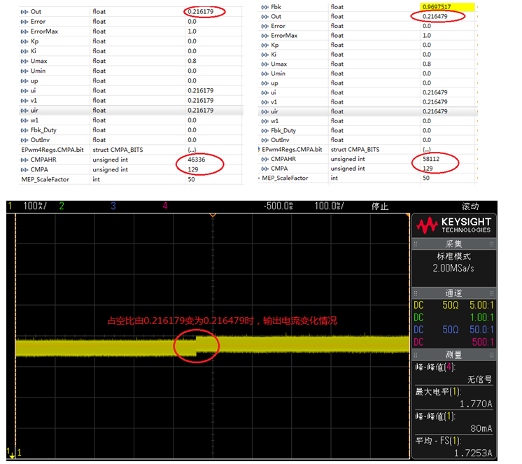
| 0.216179 | 0.003 | 129 | 46336 | 1.3 | 1.6 | 600 |
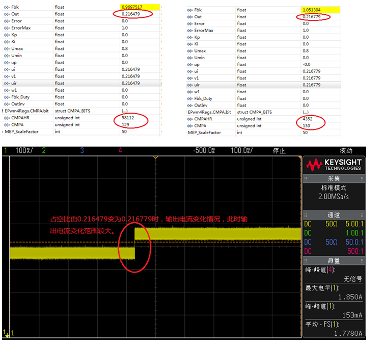
| 0.216479 | 0.003 | 129 | 58112 | 1.4 | 1.8 | 600 |
| 0.216779 | 0.003 | 130 | 4352 | 2 | 2 | 600 |
There will always be a big jump of current at the increment by 1 of CMPA.
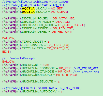
The setting is as below, auto conversion is enabled.
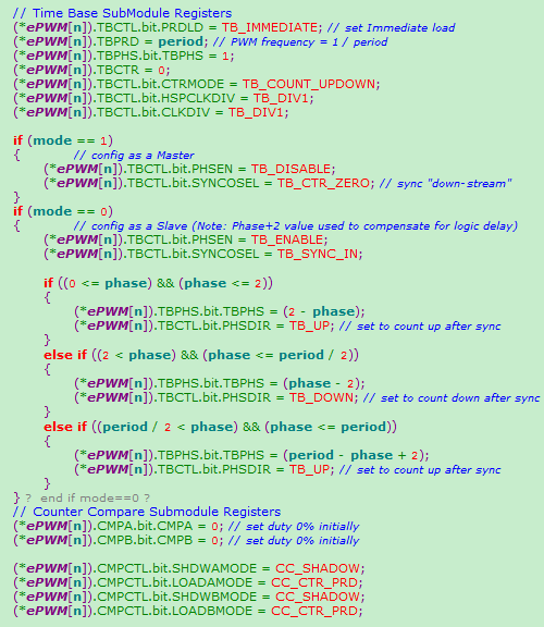
EPWM1Regs.CMPA.all=(Uint32)((float)DutyToCmpCst*(dutycycle));
DutyToCmpCst=TBPRD<<16=600*65536.
1.Duty cycle jump from 0.215279 to 0.215579: waveform is average current
2.Duty cycle jump from 0.215579 to 0.215879:
3.Duty cycle jump from 0.215879 to 0.216179:
4.Duty cycle jump from 0.216179 to 0.216479:
5.Duty cycle jump from 0.216479 to 0.216779:
So we suspect the duty cycle is not incrementing as we expected, but we don't know where are things wrong.

