This thread has been locked.

If you have a related question, please click the "Ask a related question" button in the top right corner. The newly created question will be automatically linked to this question.

TMS320F28377S: i2c master frequency innacuracy

Part Number: TMS320F28377S

Hello,

In a new board design with TMS320F2837xS microcontroller we´re having issues with i2Ca clock frequency.

According to the documentation; Fmod = SYSCLK/(I2CPSC+1). We have a 200 MHz SYSCLK and want to fix the Fmod in 10 MHz (datheet specs 7MHz < Fmod < 12 MHz) so we calculate I2CPSC = 19.

We want to fix the i2C to 400 kHz, so Tmst = 2.5 us.

We calculate then the following parameters:

ICCH = 7

ICCl = 8

Since I2CPSC > 1 --> d = 5

That should give us a Tmst = (5+7+5+8)/10000000 = 2.5 us

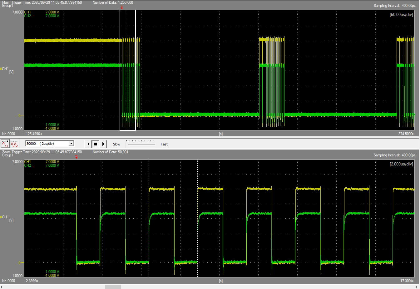
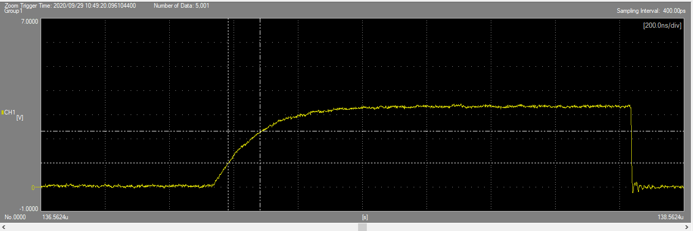
We write this in both I2CA and I2CB and measure 400 kHz in I2CB (which is correct) but 384 kHz in I2CA. We´ve measured that ICCH in I2CA has one unit error (seems like d is 6 instead of 5) and in fact, if we write ICCH = 6 instead of ICCH = 7 in this register the frequecy is 400 kHz.

Any tips on what could be happening?

Thanks in advance.

  • Hi Bernardo,

    Which GPIOs of the F2837x are you using for I2CA and I2CB? Are there any differences in what I2CA and I2CB signals are being connected to and how you're testing them?

    This issue sounds somewhat similar to the one below. Using different GPIOs for the same I2C module had shown different results in the prior debug.

    https://e2e.ti.com/support/microcontrollers/c2000/f/171/t/921836

    I'll try replicating the issue and get back to you tomorrow.

    Best,

    Kevin

  • Hi Kevin,

    We´re using GPIO42 and GPIO43 for I2CA and GPIO40 and GPIO41 for I2CB. There are differences in what I2CA and I2CB are connected to, since I2CA is a 3V3 I2C bus with four ICs (RTC, EEPROM, FRAM and Temp and %HR Sensor) and I2CB is a 5V bus connected to 2 ICs (one PCA9539DW I/O expander and a DAC).

    In order to adapt I2CB to 5V we use a level shifter for the SDA and a SN74HCT244PW for SCL.

    We´re testing them with the same oscilloscope. Both SDA and SCL waveforms are ok but i2CA shows 384 kHz instead of 400 kHz. With the same configuration parameters i2CB shows 400 kHz.

    Br,

  • Hi Br,

    I tested I2CA, GPIO104/105 (didn't have access to 42 and 43 on my board), and I2CB, GPIO40/41, on a F2837x. Both showed 400 KHz properly with your configuration. If I can find a board that brings out GPIO 42 and 43 I'll try that as well, in case it 's something specific to those pins.

    Do the signals on the oscilloscope look physically different when comparing I2CA to I2CB? Other than the frequency that is. Could you provide scope shots zoomed in on the SCL signal for both cases to compare?

    In your set up is it possible to test with just one slave device on the I2CA bus?

    Best,

    Kevin

  • Hi Kevin,

    Attached you can find the following captures:

    1.- I2CA / ICCH = 6 ICCL = 8 (with the one temp unit corrected). Freq is 400 kHz and waveform seems ok:

    2.- I2CB / ICCH = 7 ICCL = 8. Configuration at it should be, CH1 is signal before adapting the levels to 0-5V and CH2 after. As you can see waveforms are ok and freq is also 400 KHz

    In order to test with just one slave, I would have to remove the other three. Of course its possible but I´m not really sure if the problem is related to the slaves.

    In case you recommend doing this test, what slave should I leave mounted?

    Thanks and Br,

  • Hi Kevin,

    We´ve also observed unwanted peaks on SCL and according to SPRZ422I this happens because SDA and SCL outputs are implemented with push-pull 3-state output buffers ratherthan open-drain output buffers as required by I2C.

    We´re experimenting this behaviour only in I2CB bus (which has no slaves connected from the DSP to the Buffer we use to adapt levels):

    Although it seems it won´t cause an issue on the SDA I would like to limit the current. According to SPRZ422I series termination resistor should be located near SCL and SDA terminals according to Fig7 of this document. I was wondering which Rst value is recommended in order to implement it in the desing.

    Thanks!

  • Hi Bernardo,

    Thanks for providing the waveforms, both cases look pretty clean and OK to me. The I2CA signals have longer rise times compared to the I2CB, but that shouldn't impact clocking at 400 KHz.

    If it isn't easy to add / remove slave devices on your setup I would hold off on testing with fewer slave devices. I will try and locate a board that I can test the GPIOs 42 and 43 on and get back to you with the results next week.

    Bernardo de Riva said:
    We´re experimenting this behavior only in I2CB bus (which has no slaves connected from the DSP to the Buffer we use to adapt levels):

    This might be because the I2CA lines have more resistance / capacitance on the lines with the numerous slaves connected.

    Bernardo de Riva said:
    I was wondering which Rst value is recommended in order to implement it in the desing.

    NXP's I2C spec has some guidance on maximum allowable series resistance on the lines. It will depend on the pull-up resistance, voltage level, and bus capacitance on the lines. See Section 7.3 "Series protection resistors" of the spec below for details.

    https://www.nxp.com/docs/en/user-guide/UM10204.pdf

    The series resistance value shouldn't be very large based on the info in the spec, maybe around 60-75 ohms depending on the pull-up resistance / bus capacitance. It's best to test and check waveforms before settling on a final value.

    Best,

    Kevin

  • Hi Bernardo,

    I tested I2CB on GPIO2/3 and saw a similar response to what you have on GPIO42/43. Using your original configuration below I measured 370KHz.

    ICCH = 7
    ICCl = 8

    I was able to measure 400KHz with the below however:

    ICCH = 6
    ICCl = 7

    Seems like the 'd' value equals 6 for certain I2C pins. Will need to investigate further to know for sure.

    Best,

    Kevin

  • Hi Kevin,

    Thanks for your answer. I will wait for further investigation in order to set different parameters for the i2C or change the pins to GPIO104/105.

    Br,

  • Hi Bernardo,

    I've sent the details to our design team to better understand the behavior. I will update you when I have information to share. It will likely take a few days for them to get back to me.

    Best,

    Kevin

  • Ok,

    Thanks again.

    Br,

  • Hi Bernardo,

    Sorry for the wait, this is still being looked into further by our team.

    Best,

    Kevin

  • Hi Kevin,

    Any news about this issue? We´re about to launch a new board and it would be interesting to know if it is recommended to change the i2C pins to solve the problem or we can keep the design as it is.

    Thanks in advance.

  • Hi Bernardo,

    I have pinged the design team again to see if there are any concerns using GPIO42/43 for I2CA. I think you should be OK to use them in your design, but let me confirm with them. I will update you tomorrow.

    Best,

    Kevin

  • Hi Bernardo,

    What value pull-up resistor are you using on your I2C lines? I tried testing GPIO2/3 and GPIO42/43 again, this time with a stronger pull-up (lower resistance), and was able to measure the expected 400 KHz.

    Also, do you have the internal GPIO pull-up enabled or disabled for the I2C pins in your software?

    Best,

    Kevin

  • Hi Kevin,

    We´re using 3k3 pullups (approx. 1 mA) which I consider quite a strong pull up according to the i2C standards. Please correct me If I´m wrong.

    We have, in both i2CA and i2CB, internal pullups enabled, since we considered that if anything happens to the external pullups it would be better to leave the bus in a recesive state.

    Br,

  • HI Bernardo,

    Please be aware that Kevin is away from work today.  He will respond back tomorrow.


    Thank you,
    Brett

  • Hi Bernardo,

    Bernardo de Riva said:
    We´re using 3k3 pullups (approx. 1 mA) which I consider quite a strong pull up according to the i2C standards. Please correct me If I´m wrong.

    The appropriate resistor value will depend on the amount of capacitance on the I2C bus. You can find some guidance in the App Report below:

    https://www.ti.com/lit/slva689

    I'll note that in my latest tests I had reduced the external pull-up resistor value from 2.4k to 1.3k to reach 400 KHz (without the internal pull-up enabled).

    Bernardo de Riva said:
    We have, in both i2CA and i2CB, internal pullups enabled, since we considered that if anything happens to the external pullups it would be better to leave the bus in a recesive state.

    I believe this is fine. Using the internal pull-up along with the external pull-up should lead to a stronger pull-up overall. Probing the I2C lines to check that the rising edges look clean may be a good thing to verify.

    Best,

    Kevin

  • Hi Kevin,

    I´ve made the following calculations:

    I´ve measured, in the clock, a 10% to 90% rise time of 264 ns and 300 ns in data with 3k3 pullup resistors.

    This leads to a bus capacitance of 36.36 pF - 45.45 pF, which more or less matches the number of ICs that I have in the i2C BUS (4 ICs when generally speaking you can consider 10 pF per IC, please correct me if I´m wrong).

    I see that we´re quite on the limit of the maximum recommended rise times, so I´m going to lower the pullup values and re-check the i2c frequency once i´m sure that I´m ok in both rise-times and bus capacitance for 400 kHz working mode.

    Thanks Kevin, I´ll come back soon with new measurements.

    Br,

  • Hi Kevin,

    I´ve followed the document you´ve sent me and I have the following conclusions, please confirm them if possible:

    SCL:

    Rise time (0.3Vcc - 0.7Vcc) = 100 ns

    Rp = 3k3 +- 1%

    Cbus = 39.4 pF

    Waveform seems ok

    SDA:

    Rise time (0.3Vcc - 0.7Vcc) = 123 ns

    Rp = 3k3 +- 1%

    Cbus = 48.4 pF

    Waveform seems ok

    I think that it should work ok with this pullups values. Anyway, I will try with stronger pullups and see if it starts working ok

    Br

  • Hi Bernardo,

    I'm not certain how you derived your bus capacitance values from your R_p and measured rise time, as below. The 10pF per device seems like a good estimate, but may depend on the specific device. There's also the trace length which adds some capacitance to the bus lines.

    Bernardo de Riva said:

    I´ve measured, in the clock, a 10% to 90% rise time of 264 ns and 300 ns in data with 3k3 pullup resistors.

    This leads to a bus capacitance of 36.36 pF - 45.45 pF, which more or less matches the number of ICs that I have in the i2C BUS (4 ICs when generally speaking you can consider 10 pF per IC, please correct me if I´m wrong).

    To me, I'm not sure if (0.3Vcc - 0.7Vcc) for rise time is correct, since we're looking specifically at the master device. 10% - 90% or maybe (0 - 0.7Vcc) seems more correct to me (i.e. time master device lets go of the SCL line to when V_IH is read). Note that master I2C devices both drive and read the state of SCL.

    Try lower resistor values, maybe around 2k ohm, and let me know how that works.

    Best,

    Kevin

  • Hi Kevin,

    I´ve just compared i2CA with 3k3 and 2k pullup resistors and you were right. With 2k resistors I am able to reach 400 kHz with no issue. With 3k3 I have 384 kHz with the same DSP configuration, so it seems my issue is resolved.

    Thanks for your help!

    Br,

  • Hi Bernardo,

    That's good to hear. When you probe the signals if the rising edges look clean and good with the new pull-up resistor value then you should be all set.

    Best,

    Kevin