Hello.
I am looking into the implementation of peak current control for a DC/DC converter. I am looking at the document "Peak Current Control Realization for Boost Circuit Based on C2000 MCU", found here:
At page 10, looking at "Slope Compensation Code", I want to to understand mSlope_Com correctly. I am planning on using the F28069 device, and I'm reading the "TMS320x2806x Piccolo Technical Reference Manual".

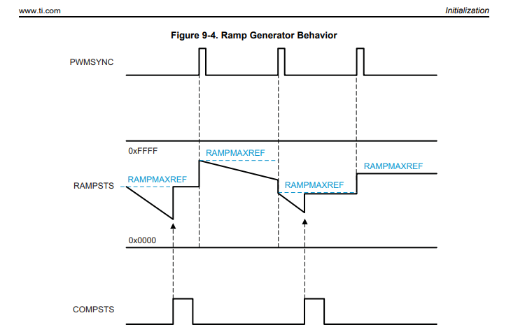
What value should I set to "RAMPMAXREF_SHDW"? In the code example it is set to "(UINT16)(1024<<6);" during the Comparator setup code. Why? Then, in the end of the Slope Compensation Code, "RAMPMAXREF_SHDW" is set to "Ref", i.e the current reference. How should the "Ref" be set? If I want a current I_ref, then I need to set the "Ref" to something higher than I_ref, so that the compensated reference goes down to my desired current Iref to meet my sampled current at the right time. Or maybe I am misunderstanding how the compensated referencing works. Could you explain?
I also do not understand why something is written to "DACVAL" at the end of the Slope Compensation Code. Isn't the DAC output automatically changed by "RAMPSTS" as the ramp is subtracting at every PWMSYNC?