This thread has been locked.

If you have a related question, please click the "Ask a related question" button in the top right corner. The newly created question will be automatically linked to this question.

TMS320F28075: SPI sends no output whatsoever, while bitbanging approach works

Part Number: TMS320F28075
Other Parts Discussed in Thread: C2000WARE

I am trying to communicate to an encoder using SPI, and am running into trouble in getting any sort of output at all. I have to use SPI B due to the architecture of my board, and the microcontroller is the master. As the title mentions, I have also tried using a bitbanging approach using the output pins as GPIO, and it works perfectly well, and I can scope the return signal on the MISO line and get the appropriate communication from the encoder.

The problem is that when I switch off of GPIO to SPI, I am not able to have any sort of output on any on the pins, including the STE and CLK lines. They just stay on whatever default value they were at (depending on if I have the pull up enabled or disabled, which I have tried various combinations of). I currently have a barebones approach without interrupts or FIFO enabled, but have tried both of these options as well with the same effect. I am just trying to get any communication at all before I start to make things more complicated.

Because the bitbanging works, I am assuming I am missing something quite obvious in the setup. I will include absolutely every line of code having to do with SPI, including all setup, so please do let me know if there is anything I am missing or messing up in the foundations! Thank you, and the code is below.

First, I set up the GPIO and peripheral clock. I have tried various pull up enable combinations to no effect, as I mentioned.


   CpuSysRegs.PCLKCR8.bit.SPI_B   =1; //Motor Encoder Through SPI


         EALLOW;

   GpioCtrlRegs.GPBPUD.bit.GPIO58 = 0;   // Enable pullup on GPIO58

   GpioCtrlRegs.GPBPUD.bit.GPIO59 = 0;   // Enable pullup on GPIO59

   GpioCtrlRegs.GPBPUD.bit.GPIO60 = 0;   // Enable pullup on GPIO60

   GpioCtrlRegs.GPBPUD.bit.GPIO61 = 0;   // Enable pullup on GPIO61

   GpioCtrlRegs.GPBQSEL2.bit.GPIO58 = 3; // asynch input

   GpioCtrlRegs.GPBQSEL2.bit.GPIO59 = 3; // asynch input

   GpioCtrlRegs.GPBQSEL2.bit.GPIO60 = 3; // asynch input

   GpioCtrlRegs.GPBQSEL2.bit.GPIO61 = 3; // asynch input

       EDIS;

   GPIO_SetupPinMux(58, GPIO_MUX_CPU1, 6); //SPIB

   GPIO_SetupPinMux(59, GPIO_MUX_CPU1, 6);

   GPIO_SetupPinMux(60, GPIO_MUX_CPU1, 6);

   GPIO_SetupPinMux(61, GPIO_MUX_CPU1, 6);


Then, there are the settings register initialization:


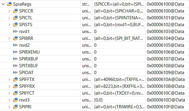
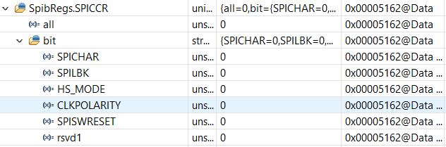
SpibRegs.SPICCR.bit.SPISWRESET = 0;     // start reset at 0


   SpibRegs.SPICCR.bit.SPICHAR = 0x0F;     // 16-bit char bits

   SpibRegs.SPICCR.bit.CLKPOLARITY = 0;   // polarity normal

   SpibRegs.SPICTL.bit.CLK_PHASE = 1;     // delay phase

   SpibRegs.SPICTL.bit.MASTER_SLAVE = 1;   // master mode

   SpibRegs.SPICTL.bit.TALK = 1;           // enable talk


   SpibRegs.SPIBRR.all =0x000F;           // Baud rate


   SpibRegs.SPICCR.bit.SPISWRESET = 1;     // Relinquish SPI from Reset


And finally, the extremely barebones communication loop. I have tried waiting for interrupts, etc. as all the examples indicate to do, but they all end up hanging on that condition. This is occurring at 1KHz:


   SpibRegs.SPITXBUF = (Uint16)(0xFFFF); //send all high data to request current motor position


   SpiRx = SpibRegs.SPIRXBUF;


Like I mentioned, this causes absolutely no change on any of the lines, including the STE and CLK lines, which stay at default value. Any help would be much appreciated!

  • Hi Fred, 

    It looks like your pin mux configuration is incomplete. Table 4-6 (GPIO Configuration for High-Speed SPI) lists the GPIO mux configuration for SPIB. Try replacing the mux configuration in your code with this:

        GpioCtrlRegs.GPBGMUX2.bit.GPIO63 = 3; // Configure GPIO63 as SPISIMOB
        GpioCtrlRegs.GPBMUX2.bit.GPIO63 = 3; // Configure GPIO63 as SPISIMOB
    
        GpioCtrlRegs.GPCGMUX1.bit.GPIO64 = 3; // Configure GPIO64 as SPISOMIB
        GpioCtrlRegs.GPCMUX1.bit.GPIO64 = 3; // Configure GPIO64 as SPISOMIB
    
        GpioCtrlRegs.GPCGMUX1.bit.GPIO65 = 3; // Configure GPIO65 as SPISOMIB
        GpioCtrlRegs.GPCMUX1.bit.GPIO65 = 3; // Configure GPIO65 as SPISOMIB
    
        GpioCtrlRegs.GPCGMUX1.bit.GPIO66 = 3; // Configure GPIO66 as SPISOMIB
        GpioCtrlRegs.GPCMUX1.bit.GPIO66 = 3; // Configure GPIO66 as SPISOMIB
    

    Note, I have not tried this on my end.

  • Hey Gus, thanks so much for getting back to me. Unfortunately, the fix you mentioned will not work, as I am using pins 63-66 for other purposes, and must use 58-61 for the SPI. I am not sure which table you are referring to, but the MUX settings table that I am referencing mentions to set each of these pins to 6 in order to use SPI (I do not requre high speed mode, to my knowledge, and am just trying to use the ordinary SPI). To this end, I am using the following code, which is at the end of the GPIO setup section in my original post.

    GPIO_SetupPinMux(58, GPIO_MUX_CPU1, 6); //SPIB
     
    GPIO_SetupPinMux(59, GPIO_MUX_CPU1, 6);
     
    GPIO_SetupPinMux(60, GPIO_MUX_CPU1, 6);
     
    GPIO_SetupPinMux(61, GPIO_MUX_CPU1, 6);
    Beforehand, I was setting GPCGMUX and GPCMUX directly (to 6) as you are, but the user manual mentions that there can be issues with setting other registers, so I switched to the builtin function instead just in case. Either way, I have confirmed via JTAG that after initialization, the GPCGMUX and GPCMUX pins are properly set to 6 with both methods. 
  • Hi Fred,

    Fred Etingen said:
    Unfortunately, the fix you mentioned will not work, as I am using pins 63-66 for other purposes, and must use 58-61 for the SPI.

    You are absolutely correct! I did mistakenly give you the settings for a different SPIB mux option.

    Fred Etingen said:
    I am not sure which table you are referring to, but the MUX settings table that I am referencing mentions to set each of these pins to 6 in order to use SPI (I do not requre high speed mode, to my knowledge, and am just trying to use the ordinary SPI).

    I was referring to the table in the device datasheet. Minor point (irrelevant for this discussion), the high-speed mux options can be used for normal speed configuration.

    Fred Etingen said:
    Beforehand, I was setting GPCGMUX and GPCMUX directly (to 6) as you are

    Fred Etingen said:
    I have confirmed via JTAG that after initialization, the GPCGMUX and GPCMUX pins are properly set to 6 with both methods. 

    A couple of points:

    - The muxing for GPIO58/59/60/61 is controlled through GPBGMUX2 and GPBMUX2. (See GPBGMUX2 and GPBMUX2 register description in F2807x TRM, SPRUHM9)

    - Each bit field in those registers needs to be set to 10b. For example, for GPIO58=SPICLKB, GPBGMUX2[21:20] = 01b and GPBMUX2[21:20] = 10b.

    Having said all that, it is valid (and simpler) to use GPIO_SetupPinMux() to configure the pin muxing and I don't see anything wrong there. You may just want to confirm the GPBGMUX2 and GPBMUX2 registers end up with the expected value. 

    I can't see anything wrong with your setup. Can you try enabling loopback mode and see if you get the value you write to SPITXBUF in SPIRXBUF? 

    SpibRegs.SPICCR.bit.SPILBK = 1;

    [EDIT: Corrected typo on loop-back code snippet.]

    [EDIT: Correct GPB register info & correct TRM lit number.]

  • I apologize, you are completely right that it is GPB, it was a typo on my end in my response. In the code, I was setting and monitoring the GPB registers, and just double checked, and they are in fact being set properly. Although you mention that they should both be set to 10b, but in the manual that I am referencing it says to set the GPBGMUX to 01b and GPBMUX to 10b (resulting in the 6 I am using in the function). I am looking at http://www.ti.com/lit/ug/spruhm9f/spruhm9f.pdf on page 831, I tried looking for the document you mentioned to see if it is different but am not sure how to search for it. Are we talking about the same document or am I using an incorrect version?

    I just tried enabling the loopback and there is no change on the output side, nor does the SpibRegs.SPIRXBUF register show any signs of change, remaining at 0 for all operation, as before. 

    Also thank you for the tidbit on the high speed configuration, that is certainly handy to know for future reference!

  • Fred Etingen said:
    Although you mention that they should both be set to 10b, but in the manual that I am referencing it says to set the GPBGMUX to 01b and GPBMUX to 10b (resulting in the 6 I am using in the function).

    Yes, you are correct about the GPB register settings. My mistake. I'll post-edit my original post so future readers don't get the incorrect information.

    Fred Etingen said:
    I am looking at http://www.ti.com/lit/ug/spruhm9f/spruhm9f.pdf on page 831, I tried looking for the document you mentioned to see if it is different but am not sure how to search for it.

    You are looking at the right document. I gave the datasheet lit number rather than the TRM. I'll post-edit that too. Sigh.

    Fred Etingen said:
    I just tried enabling the loopback and there is no change on the output side, nor does the SpibRegs.SPIRXBUF register show any signs of change, remaining at 0 for all operation, as before. 

    Ok, this is very puzzling. A few things I can recommend. Try setting SPIPRI.FREE = 1, this will ensure the debugger is not playing tricks with us. If you could also screen-capture your SPI registers after the first data is sent, I can take a look to see if there is something odd there. Finally, you can try one of the SPI loopback examples in C2000ware just to make sure those work ok.

  • Haha, sorry to be annoying, I am just trying to check every detail to make sure I am not making any obvoius mistakes. As I was looking into your request to check the registers, though, I realized that there was a large issue. The GPIO settings seem to take effect just fine, but for some reason all of the registers set in the SPI settings function are not changed. I could have sworn that I have checked this before to make sure that it was taking effect, but I could be mistaken. In any case this appears to be the problem (or the first one, at least). I am calling the function that contains the SPI register changes shortly after the GPIO settings. Do you know why they might not be changing? I also am unable to change them manually through the CCS debugger, like I am with other similar registers (they immediately revert to 0). Do you know what could be hapening here?

    EDIT: Also, about the examples, I wanted to try example code when starting this but was unable to find even a single example which used the SPIA, only the SPIB. I can't use SPIA as it is wired directly to other components on the board. Do you know of any similar examples that use SPIB?

  • Fred, 

    No worries on pointing out errors. I thank you for that. 

    Ok, now we are getting somewhere. The fact that you can't write to the registers indicates to me that there is no clock to the SPIB module. I do see you have the code to set PCLKCR8.SPIB = 1 which should enable the clock. However, this register is write-protected by EALLOW, so make sure you have enabled write access before writing to it.

  • I just added the EALLOW and corresponding EDIS, but there is no change at all. It is also strange, because just before this, I am enabling the clocks for ePWM, and those modules work perfectly fine (they are all on PCLKCR2). Also, in the top right most screencap in the image, even before the EALLOW it seems that the SPI signals are being turned on (which is also somewhat strange, as I am only intentionally enabling the SPI_B). Could there be some sort of overlap or something like that? I am using CpuTimers 1 and 2 for scheudling in my code, I am not sure if that could be impacting this somehow?

  • Ok, I see now that PCLKCR8.SPIB was already set. 

    I think the best course is to try the loopback examples. To your earlier question, you should be able to comment out the GPIO configuration code in the example and run it like that. Since internal loopback is enabled, you don't need the GPIO configuration. Alternatively, you can modify the code & GPIO configuration for SPIB use. I see the following example as a good one to try.

    C:\ti\c2000\C2000Ware_3_02_00_00\device_support\f2807x\examples\cpu1\spi_loopback\cpu01

    Are you using custom board? You may want to try setting the boot mode to "wait boot mode" just to eliminate the possibility of the ROM or any other code stored in flash from changing settings on you before you load & run the example code.

  • Hey Gus, sorry for the delay. I have just gotten the example you mentioned running, with no modifications except commenting out the line which calls InitSpiaGpio(). I tried this both on the bootmode which I have been using, as well as forcing wait boot mode, and both lead to the same exact results. I will post an image of all of the SPIa registers below, but they all appear to be uninitialized, except some strange values in some of the FIFO registers.

  • Hi Fred, 

    A few questions. Did the example code return any errors? Can you verify that the CCS register window is indeed pointing to the right address? Per the device datasheet SpiaRegs start at 0x0000 6100.

  • Yes sorry for cutting out the address section of the info. It does appear to be at the correct address, though. There are no errors or warnings when building the code, either.

  • Fred,

    In the example code, does the CPU stop in error()? Have you tried a different board? 

       sdata = 0x0000;
       for(;;)
       {
            //
            // Transmit data
            //
            spi_xmit(sdata);
    
            //
            // Wait until data is received
            //
            while(SpiaRegs.SPIFFRX.bit.RXFFST !=1) { }
    
            //
            // Check against sent data
            //
            rdata = SpiaRegs.SPIRXBUF;
            if(rdata != sdata)
            {
                error();
            }
            sdata++;
       }

  • In testing whether it was reaching that error condition, I noticed something extremely strange, which is that it is not even reaching the for loop. I tracked down where it is stalling using some probing variables, and it seems that the last line that it reaches is the call for InitSysPll(XTAL_OSC,IMULT_12,FMULT_0,PLLCLK_BY_2); in the function InitSysCtrl. I have no idea what could be going wrong with this, and even more strangely, I am sure that in my original code, it is getting past all of the initialization and running the control loop which includes the SPI calls. Any ideas what could be happening here?

    EDIT: Also, i am unfortunately do not have access to another board. I could ask someone on my team to try to test it, but it would likely have to wait until next week. This is perfectly fine if you are convinced it is an issue with my particular chip / board, though.

  • The InitSysPll() function is setting up the clocking scheme on your device. It could be failing for multiple reasons: no external crystal oscillator, PLL not locking due to incorrect setting, etc. It would be worth you digging into the variables passed to the function to make sure they match what you board can support (the source for the function is included in C2000ware). For now, maybe you can comment that function out. Best case, the CPU and peripherals will be running very slow, but at least we get to see something working. :-)

  • Hey Gus, thanks again for the continued support. I appreciate you sticking with me, despite some fairly novice questions.

    So after changing the InitSysPll options to match ones that I had working in my main build, I was happy to see that the spi was working as intended. By this, I mean that the Tx was properly looping back to the Rx and increment in the loop with no error. This continued to be true for Spib as well, so I went to my main build and tried to replicate everything as closely as I could to how it was set up in the example. Of course, there are other sections in between which I need to setup the other peripherals on the board, but the main components from the example are all there. Unfortunately, though, although it gets through all of the initialization and into the main control loop, it is once again not changing any of the Spi registers (neither on Spia or b), instead all remaining at 0. This time it is definitely reaching those lines of code and continuing forward.

    The only major difference that I can see between the two (other than the other additional peripherals, which to my knowledge shouldn't have any interaction here) is that I am running my main code off of flash. I am not sure if there is anything to do with this that I need to be aware of when trying to match the example code. If not, I am not sure what else could be causing me to be unable to write to the Spi registers.

  • Hi Fred,

    I'm glad to hear the example code is working. I was a little worried about it not functioning. Now you have a working reference to back to if needed. :-)

    Regarding the flash vs. RAM difference, it shouldn't matter. However, there is a CCS build configuration which runs that example code from flash if you want to try it.

    Regarding your main code, the fact you don't see the SPI registers changing is really puzzling. I would suggest you load your code and stop it right after it enables the SPI clock (PCLKCR8). I'm guessing this is relatively early in your code (if not, just add that one line shortly after entry to main()). Then use CCS to poke at the SPIB registers. If you can modify the SPIB registers at that point then maybe some other line in your code that comes later is causing problem. You can keep repeating the process, stopping at some point later in your code, until you identify the culprit. If you still can't write the SPIB registers shortly after entering main and enabling the SPI clock then we can figure something else out.

  • Hey Gus,

    To start with the good news, I managed to get it running off of flash, and it works perfectly well (the example code, that is). I knew about the other configuration, but was getting an error, but after your confirmation that it should work, I poked around a bit more and got it running. For the bad news, I confirmed that the first line of code in my main function is indeed the call to InitSysCtrl();, effectively making the peripheral clock enable the very first thing that happens. I set a hardware breakpoint directly after, and even still, cannot change any of the Spi a or b registers. I did confirm that the clock is enabled for both, and in the breakpoint, can toggle it through the same peripheral clock register, but can't modify the Spi registers themselves. 

  • Hi Fred,

    Can you check the status of the SPI_A/B bits in the SOFTPRES8 register under the DevCfgRegs group in CCS? I'm wondering if the SPI modules are being held in reset. This would definitely prevent writes to the SPI registers. By default these bits should be 0 (SPI peripheral not in reset).

  • It appears that they are in fact set at 0. This is at the breakpoint just after the first line, as in my previous message. I am not sure if it matters, but these are also toggleable (I set the SPI_B bit to 1 and then back to 0, and it proceeded the same as before).

  • Fred,

    Really sorry we haven't been able to figure this out yet. Rest assured we'll get to the bottom of the problem one way or another.

    Just to summarize, we know that with the SPI example code you are able to read and write to the SPI registers. This is with the code running from RAM and from FLASH. With your code, even after verifying the SPI is out reset (SOFTPRESx) and has a clock (PCLKCRx) you cannot write to the SPI registers. So the question is what is different between your code and the example code?

    I don't have any HW with the particular device you are using handy so I can't replicate what you are seeing. However, I do have a different device LaunchPad and I have been poking at SPI registers. I can definitely see that with reset high (SOFTPRESx) and clock off (PCLKCRx) the SPI registers are not writeable. However as soon as the clock is enabled, the SPI registers become writeable, which is what we would expect.

    The only thing I'm thinking is a possible difference in the GEL file??? Check which GEL file the example code uses and the one your main code uses. Are these the same? Are there any differences?

    For reference, the GEL file used in the example should be located in:

    <ccs_install_dir>\ccs\ccs_base\emulation\gel\f28075.gel

    By default the OnTargetConnect() function should run when you start the debug session. I'd start there.

  • Hey Gus,

    No need to apologize at all, I am very glad for the continued support despite the annoyance of this issue. I also apologize for the delays in getting back to you, I have had a lot of parallel things coming up, but try to get back to you as soon as I can.

    So I am a bit confused on where to find the gel file used, it is not listed as part of the build log (at least not that I could see) but if I am correct that it is the one listed below in the target configuration screen, it seems to be that it is the same one that you mentioned should be used for the example. If this is not the correct one to be looking for, if you could point me towards how to find the gel file I will gladly get you the correct information.

    Also, I should add that I am adding several functions to ram to increase their performance, and previously had a large chunk of the ram reserved for storage. Could it be that this is somehow causing interference with the registers? Probably a dumb question, but I just want to make sure there isnt some piece of information that I don't even know to share that could be pivotal.

    EDIT: To clarify, when I say that I PREVIOUSLY had a large section of ram sectioned off, I have removed the code to reserve this section of ram in one of my more recent tests just in case, and it did not appear to have made a difference.

  • Fred,

    Fred Etingen said:
    So I am a bit confused on where to find the gel file used, it is not listed as part of the build log (at least not that I could see) but if I am correct that it is the one listed below in the target configuration screen, it seems to be that it is the same one that you mentioned should be used for the example. If this is not the correct one to be looking for, if you could point me towards how to find the gel file I will gladly get you the correct information.

    Regarding the GEL file, his is used by CCS to automate some functionality. You can read more about it at this link. These functions are not part of the actual executable code that runs on the MCU. These are executed by CCS directly.

    You specify the GEL file to use in the target configuration file, as you already discovered. Once you launch a debug session (i.e. launch the target config file *and* connect to the CPU core), you will see two menu options in CCS: Tools>GEL Files tells you which GEL file you are using and Scripts shows you which menu functions have been defined in your GEL file (if you read the GEL file you should see hotmenu items that correspond to these functions).

    There are some GEL functions that execute automatically. For example, OnTargetConnect() executes when you connect CCS to the target device. Among other things, this function calls several memory map functions that basically tell CCS which memory regions it is allowed to access. You may have seen a message pop up on CCS that reads "Memory Map Initialization Complete". This is the OnTargetConnect() function executing.

    So long story short, I'm interested to know if the example code target config file and your main code target config file are using different GEL files. 

    Fred Etingen said:
    Also, I should add that I am adding several functions to ram to increase their performance, and previously had a large chunk of the ram reserved for storage. Could it be that this is somehow causing interference with the registers? Probably a dumb question, but I just want to make sure there isnt some piece of information that I don't even know to share that could be pivotal.

    I'm not 100% sure what you mean here. Are you saying you had some RAM reserved in the linker command file and you were copying some functions from flash to that RAM section during run time? That should be ok. In any case it looks like you disabled that and the problem is still there.

  • Hey Gus,

    Thanks for the info! That is very good to know, and far outside of my area of knowledge so it is great to get some insight on it for future reference. Using the menu option you mentioned after starting a debug session, it does in fact appear that both GEL files are the same. Specifically, they use the f28075.gel Version 4.00.0, which for me is stored in the ccs_base in ccs version 9.2.0. 

  • Hi Fred,

    I've written a GEL script which can maybe help us catch this little poltergeist that has been playing with us. :-)

    I've tested on my board (with a different device since I don't have the F28075). The addresses are the same so it should work on your end. The script is pretty simple. It will just try to enable the SPI clock, release reset, and then try to write to a SPIB register.

    menuitem "Poltergeist Catcher"
    hotmenu SpibTest()
    {
        // Start Test
        GEL_TextOut("\nSPIB Test Start...\n");
        
        // Read & print registers
        GEL_TextOut("CpuSysRegs.PCLKCR8: 0x%x\n",,,,, *(unsigned long *)0x0005D332);
        GEL_TextOut("DevCfgRegs.SOFTPRES8: 0x%x\n",,,,, *(unsigned long *)0x0005D092);
        GEL_TextOut("SPIBRegs.SPICCR: 0x%x\n",,,,, *(unsigned long *)0x00006110);
        
        // Set PCLKCR8.SPIB to enable peripheral clock
        *(unsigned long *)0x0005D332 |= ((unsigned long)0x01 << 1);
        // Clear SOFTPRES8.SPIB to take peripheral out of reset (should be default)
        *(unsigned long *)0x0005D092 &= ~((unsigned long)0x01 << 1);
        // Try to write to some SPI registers
        *(unsigned long *)0x00006110 |= ((unsigned long)0xF7);
        
        //Read & print registers
        GEL_TextOut("CpuSysRegs.PCLKCR8: 0x%x\n",,,,, *(unsigned long *)0x0005D332);
        GEL_TextOut("DevCfgRegs.SOFTPRES8: 0x%x\n",,,,, *(unsigned long *)0x0005D092);
        GEL_TextOut("SPIBRegs.SPICCR: 0x%x\n",,,,, *(unsigned long *)0x00006110);
    
        GEL_TextOut("...SPIB Test End\n");
    }
    

    Here are the steps to add it to the GEL file and use it.

    1. Connect your board as you normally would and fire up CCS. Do not load your code or start the debug session just yet.
    2. In CCS hit View>Target Configurations. You should see a window that pops up with "Projects" and "User Defined" target configs. Find the target config for your project (should be under "Projects"), right-click and launch. You should see the Debug perspective launch.
    3. Under "Debug", right-click on the  CPU and select "Connect to Target". CCS should now be connected to your board.
    4. Now we add the poltergeist catcher script to your GEL file. In CCS, go to Tools>GEL Files, then double-click on the f28075.gel from the "GEL Files" window to open and edit it. You can add the lines of code to the end of the file. Save the file.
    5. You can now "reload" the GEL file by right-clicking on the file in the "GEL Files" window.
    6. Now you can run the script. In CCS, select Scripts>Poltergeist Catcher>SpibTest. You will see the GEL output on the Console. Let me know what that says.

    Keep in mind that up to this point no code has been loaded or run. So this should be a pretty "clean" state for the device. If the script can successfully write to the SPIB register, then you can load your code and go to main(). I would then run the script again (only step 6 is needed now). If it fails at that point, then we know somewhere before main() something odd is happening. If it doesn't fail here, then move to a later point in your code and run the script again.

  • For reference, here is the GEL output when I run the script on my board.

    C28xx_CPU1: GEL Output:
    SPIB Test Start...
    C28xx_CPU1: GEL Output: CpuSysRegs.PCLKCR8: 0x0x00000000
    C28xx_CPU1: GEL Output: DevCfgRegs.SOFTPRES8: 0x0x00000000
    C28xx_CPU1: GEL Output: SPIBRegs.SPICCR: 0x0x00000000
    C28xx_CPU1: GEL Output: CpuSysRegs.PCLKCR8: 0x0x00000002
    C28xx_CPU1: GEL Output: DevCfgRegs.SOFTPRES8: 0x0x00000000
    C28xx_CPU1: GEL Output: SPIBRegs.SPICCR: 0x0x000000F7
    C28xx_CPU1: GEL Output: ...SPIB Test End

  • Wow Gus, I think that if there was any arguing it before, you've now well proven you're going above and beyond to help me solve this issue! Thanks so much!

    So I ran your script in 3 separate locations, first as per your instructions, then at the entrance to main, and then at a hardware breakpoint just after InitSysCtrl() and nothing else. If I am not mistaken, it seems that all 3 have the correct outputs, with the third being slightly different due to the SpiA, B, and C bits of the peripheral clock being set to 1 in the InitSysCtrl call. 

    As per gus instructions:
    C28xx_CPU1: GEL Output: 
    Memory Map Initialization Complete
    C28xx_CPU1: GEL Output: 
    SPIB Test Start...
    C28xx_CPU1: GEL Output: CpuSysRegs.PCLKCR8: 0x0x00000000
    C28xx_CPU1: GEL Output: DevCfgRegs.SOFTPRES8: 0x0x00000000
    C28xx_CPU1: GEL Output: SPIBRegs.SPICCR: 0x0x00000000
    C28xx_CPU1: GEL Output: CpuSysRegs.PCLKCR8: 0x0x00000002
    C28xx_CPU1: GEL Output: DevCfgRegs.SOFTPRES8: 0x0x00000000
    C28xx_CPU1: GEL Output: SPIBRegs.SPICCR: 0x0x000000F7
    C28xx_CPU1: GEL Output: ...SPIB Test End
    
    At main start:
    C28xx_CPU1: GEL Output: 
    Memory Map Initialization Complete
    C28xx_CPU1: GEL Output: 
    SPIB Test Start...
    C28xx_CPU1: GEL Output: CpuSysRegs.PCLKCR8: 0x0x00000000
    C28xx_CPU1: GEL Output: DevCfgRegs.SOFTPRES8: 0x0x00000000
    C28xx_CPU1: GEL Output: SPIBRegs.SPICCR: 0x0x00000000
    C28xx_CPU1: GEL Output: CpuSysRegs.PCLKCR8: 0x0x00000002
    C28xx_CPU1: GEL Output: DevCfgRegs.SOFTPRES8: 0x0x00000000
    C28xx_CPU1: GEL Output: SPIBRegs.SPICCR: 0x0x000000F7
    C28xx_CPU1: GEL Output: ...SPIB Test End
    
    After InitSysCntrl:
    C28xx_CPU1: GEL Output: 
    Memory Map Initialization Complete
    C28xx_CPU1: GEL Output: 
    SPIB Test Start...
    C28xx_CPU1: GEL Output: CpuSysRegs.PCLKCR8: 0x0x00000007
    C28xx_CPU1: GEL Output: DevCfgRegs.SOFTPRES8: 0x0x00000000
    C28xx_CPU1: GEL Output: SPIBRegs.SPICCR: 0x0x00000000
    C28xx_CPU1: GEL Output: CpuSysRegs.PCLKCR8: 0x0x00000007
    C28xx_CPU1: GEL Output: DevCfgRegs.SOFTPRES8: 0x0x00000000
    C28xx_CPU1: GEL Output: SPIBRegs.SPICCR: 0x0x000000F7
    C28xx_CPU1: GEL Output: ...SPIB Test End
    

    But what I was more surprised to see is that even after these, when looking at the registers through the debugger, the SpiB registers didn't change at all (image below was taken after InitSysCtrl and then running the script, but the same exact thing happens when I stop at entrance to main and run the script). Not only do the registers not show any change, I also am still unable to manually change them, either, even though it appears from your script that they should in fact be changing. 

  • Well, 0x0000 5162 is not the right address for SpibRegs.SPICCR, so that's why that's not matching the GEL output. I think before you had checked the SpiaRegs address and that looked ok, but I wonder if this was always the problem for SpibRegs?

    Are you pulling this register information from the CCS "Registers" or "Expressions" window? On my CCS version, I don't see the address information, so I'm just wondering if you are viewing something different.

  • Fred,

    Can you check the contents of DevCfgRegs.DC9 to makes sure that the SPI is not locked out?

    -Tommy

  • You are right, I was pulling all of my previous screenshots from the expressions tab, which up until now has never given me issues. I just checked in the registers window, and it does in fact change when I run your script! Weirdly enough though, even in this window, nothing changes when I run the initialization code which is supposed to change the various spi registers. I can, though, change it manually through the registers window. I tried to manually change all of the values in order to get them to what they would be if the initialization code went through, and then manually changed the SPITXBUF to try to send a value, and it still did not appear to do anything when I scoped the output.

  • Hey Tommy,

    It does appear that these registers correspond to the SPI working. This screenshot is taken from the expressions menu, though, which as per the previous couple of messages seems like it may be an issue? 

  • Fred Etingen said:
    You are right, I was pulling all of my previous screenshots from the expressions tab, which up until now has never given me issues. I just checked in the registers window, and it does in fact change when I run your script!

    This is weird. To be honest, I'm not 100% sure how the register map gets populated by CCS, but I think as long as your target config is setup correctly this should work fine. Maybe double check the target config file for your project OR use the one that comes with the example code you ran earlier and worked (assuming they are different).

    Fred Etingen said:
    Weirdly enough though, even in this window, nothing changes when I run the initialization code which is supposed to change the various spi registers.

    This makes me believe your code is not building or linking the right header files. Maybe your code is writing to the wrong register addresses. You should be able to tell by browsing the disassembly window as you step through the SPI init code. Or, maybe easier, you can also review the .map file for your project to see where the SpibRegs are getting linked to.

    Fred Etingen said:
    I tried to manually change all of the values in order to get them to what they would be if the initialization code went through, and then manually changed the SPITXBUF to try to send a value, and it still did not appear to do anything when I scoped the output.

    You probably need to set the FREE bit in the SPIPRI register to allow the SPI to operate even when the emulator has halted the processor. 

  • Hey Gus,

    Sorry for the delay. I had an issue come up that unfortunately took precedence and only got a chance to come back to this today. So I checked out the .map file and it does in fact look like it is not reflective of the values listed in the user manual. I have no idea how this happened, and also am not really sure of the fix. 

    If I am reading both of these correctly, then it appears from the manual SpiRegs should start at 6100

    SpiaRegs SPI_REGS 0x0000 6100 0x0000 610F Yes Yes Yes

    SpibRegs SPI_REGS 0x0000 6110 0x0000 611F Yes Yes Yes

    SpicRegs SPI_REGS 0x0000 6120 0x0000 612F Yes Yes Yes

    And from the manual it appears they are being set to start at 5122

    1 00005122 _SpiaRegs
    1 00005162 _SpibRegs
    1 000051a2 _SpicRegs

    Is the fix for this to update the .map file to a correct one or would the change have to come from somewhere else? And if it is the .map file, could I just take the one from the example and use that?

  • Hi Fred,

    Ok, so this is the reason why you haven't been able to get your code to write to the SPI registers: there is something wrong in your linker command file. The SpiaRegs variable is pointing to the wrong address.

    Below is a recap of what the linker command file does. I excerpted this from the F28004x Microcontroller Workshop Manual if you are interested in reading more.

    Fred Etingen said:
    Is the fix for this to update the .map file to a correct one or would the change have to come from somewhere else? And if it is the .map file, could I just take the one from the example and use that?

    You'll need to fix your command file. The .map file is an output of linking process. It is only a semi-log file summarizing the results; it has no effect on actual operation.

    Unfortunately fixing the command file is a bit beyond my area of knowledge. I suggest you mark this thread as resolved and start a new thread describing this issue and somebody with more experience in the matter will be able to assist you. 

    If after fixing this issue you have additional questions on programming the SPI, you can start a new thread and we can assist you further.

  • Ok, I will do just that. Thanks again for sticking with me for this long and helping me out with this much of the process!! I really appreciate all of the work you've put in, throughout the twists and turns of the issue.