This thread has been locked.

If you have a related question, please click the "Ask a related question" button in the top right corner. The newly created question will be automatically linked to this question.

TMS320F28335: Watchdog reset problem

Part Number: TMS320F28335

Hi,

I'm using a control/command card with a TMS320F28335 which someone designed before I was in the company.

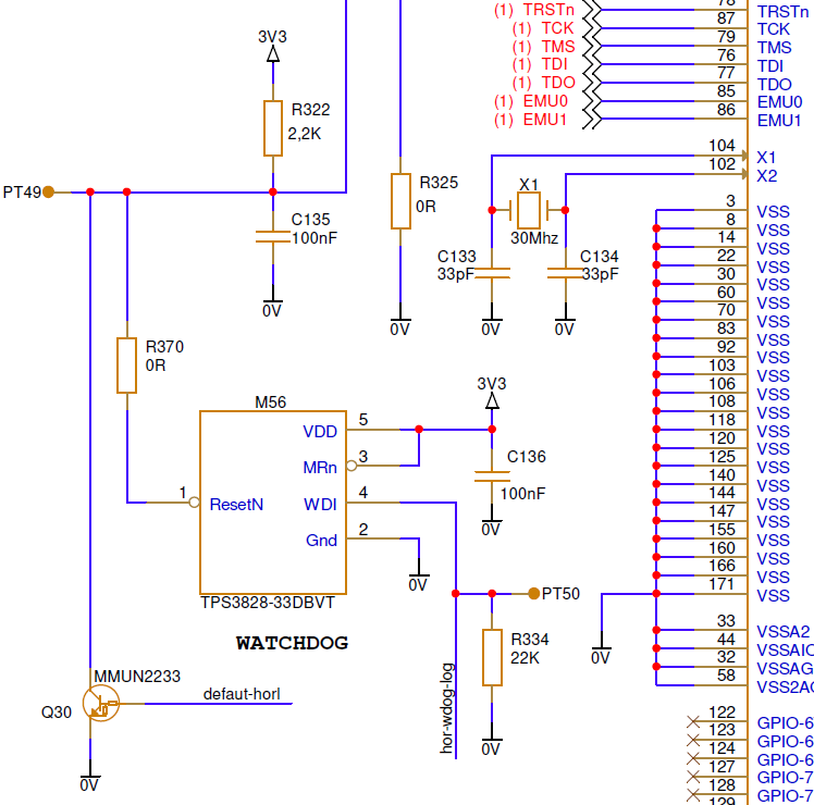
In the software, a pulse is generated via a GPIO in order to to prove that the software is running correctly. This signal is connected to the WDI pin of the TPS3828-33DBVT device (you can see it on the joined picture).

The problem is when I want to program/debug the software through the JTAG connector : i'm not able to do it because the TPS3828-33DBVT reset the µC every 1-2s because there is non signal coming from the µC.

I don't know if the implemented solution is the good one and if we use correctly the TPS3828-33DBVT...

I'm looking for a solution that allow me to program the µC when the JTAG is connected. Any idea ?

Thanks for your help 

  • Guillaume,

    Thanks for reaching out to the E2E forum.

    I think for debug we can do the following:

    1)De-populate R334 22kOhm pulldown

    2)For the GPIO that is connected from the F28334 to the TPS do the following:

    a)Change from output mode to input mode(GPxDIR register = 0 for the GPIO in question)

    b)Disabled the internal Pullup(PUDIS = 1 for the associated GPIO

    This should allow the internal signal of the TPS drive the WDI signal automatically while you debug.

    We do have the ability on C2000 to invoke "Real-Time Debug" mode, which allows the time critical ISRs to continue to be serviced while you debug other code; however, since you will be re-loading/re-programming we can't utilize this feature since during that time all interrupts would need to be disabled.  If there was no code loads we could use that as well.

    Finally, I will add that the F2833x has its own internal Watchdog timer that will pull XRSn low when it times out.  Given that the TPS is monitoring the system voltage it may have been simpler to utilize this function (WD timeout) externally as well, vs partitioning the system to have multiple sources of reset.  Or it could have been desirable to have a backup WD in addition to the on-chip timer.

    Let me know if above works, hopefully de-populating the R334 is feasible while the system is being debugged.

    Best,
    Matthew

  • Matthew,

    Thanks for your answer.

    During our tests, we have de-populated the R334 resistor and replaced it by a switch/jumper in order to programm the F28335. This solution works fine, we're able to programm theF28335.

    But the problem we have is that the switch/jumper isn't a long term solution : it will not support vibrations. So that's why we are looking for another solution.

    Best regards,

    Guillaume

  • Guillaume,

    Thanks for the additional information, I understand this is an issue for the device when it is in service, as there will be potential for reprogramming outside a debug environment.

    Based on how I've interpreted the TPS datasheet, I think you may be able to remove the PD on R334 completely/permanently.  When the F28335 configures the GPIO connected to this signal as an output(from the F28335 to the TPS), it will fault if it doesn't see the toggle in normal operation.

    When you are ready to program the device(in which case you won't be able to toggle the GPIO), if you make the GPIO pin in question as an input; the TPS should detect this as a high Z, and then its own internal signal should be able to keep things proper.  You could then switch the GPIO back to output once you are finished programming/debugging.

    There may be an alternative to this depending on which GPIO you have used to trigger the TPS.  If the GPIO on the F28335 has a PWM as a muxed function, you could set up the PWM module to toggle the pin automatically.  This should work even during programmation, as their is no ISR required.

    Finally, as I mentioned previously, you could switch to using the internal WD of the F28335 and leave R334 de-pop'd and the GPIO as an input so that it will never trigger a XRSn from that source.(The internal WD on the F28335 is capable of pulsing XRSn pin low when it times out as well).

    Best,

    Matthew