Hi guys,
I need to read 5 ADC chips (5 slaves) (MCP3208) using the SPI interface with a sampling time of 0.00013s. Each ADC has 8 channels (I need to read 36 of 40 channels). I need to do this using Matlab Simulink R2017b.
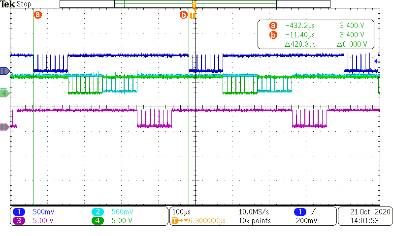
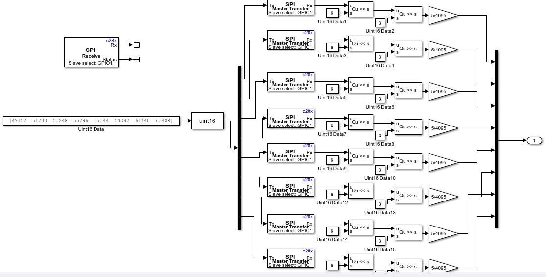
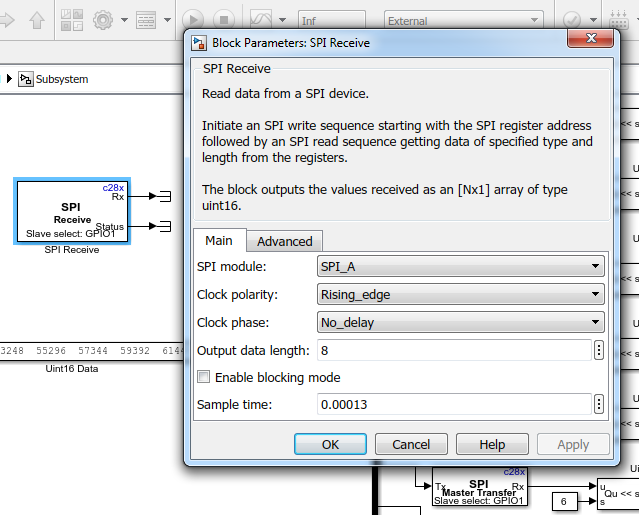
I am able to read 8 channels (1 ADC) within 0.00013s using the attached model. Also, I am able to read 16 channels but the sampling time is reduced to half of the required time (0.00013s) automatically (I have set each "Receive Block" with 0.00013 So SPI took 0.00026s to read 16 channels). Please see the attached. Please note that even if the system is working with 16 channels but I am still getting this error "Not enough memory on the target to process the packet: EXT_SETPARAM" (I have changed the "Duration" of the "External Mode" setting from 1000 to 5 but I am still getting the same message).
So my questions are
1) Is my Simulink Model (www.mathworks.com/.../617713-read-5-adc-slaves-using-spi-interface-via-launchxl-f28379d-simulink) is the right way to read ADC chip?
2) How can I read 5 ADCs (5 GPIO are used to read 36 channels) within 0.00013s?
Please note that I am getting the following errors when
1) I set the "sampling time" of the "Receive Block" as 0.000026s (=0.00013/5).
The error is:
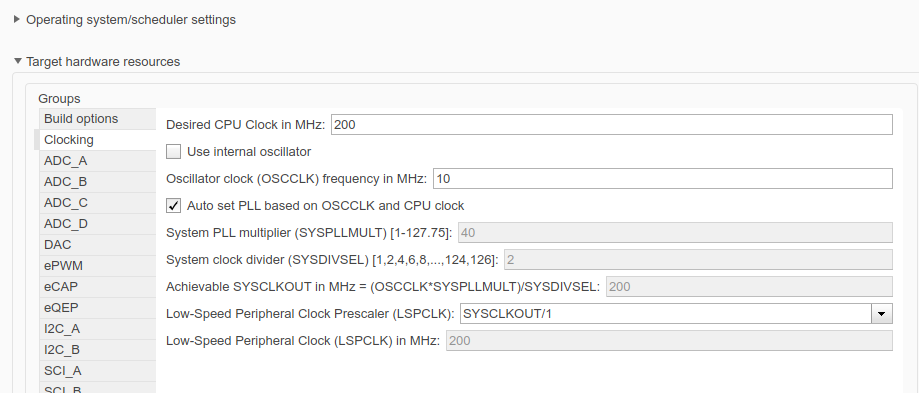
"Invalid setting for fixed-step size (1.0E-5) in model 'SPI_C'. All sample times in your model must be an integer multiple of the fixed-step size.
Component: Simulink | Category: Model error
The sample time period (2.6E-5) of 'SPI_C/Subsystem/SPI Receive' is not an integer multiple of the fixed step size (1.0E-5) specified for model"
2) when I choose "enable blocking mode"
The error is:
An error occurred while executing External Mode MEX-file 'ext_comm':
Failed to connect to the target. A time-out occurred while waiting for the connection response from the target. Possible reasons for the time-out:
a) The target is not switched on.
b) The target is not connected to your host machine.
c) The application for the model is not running on the target. You might have clicked the Stop button. If the Run button is not dimmed, click it. Otherwise, click the Build button, which downloads and runs your application on the target.


Thank you in advance