This thread has been locked.

If you have a related question, please click the "Ask a related question" button in the top right corner. The newly created question will be automatically linked to this question.

LAUNCHXL-F28379D: TIDM-1011 t format encoder test

Part Number: LAUNCHXL-F28379D
Other Parts Discussed in Thread: TIDM-1011

hi expert,

I am testing T format encoder or my customer.

and I use the TIDM-1011 and F28379 Launchpad.

I can confirm the HW connection strictly according to the guide.

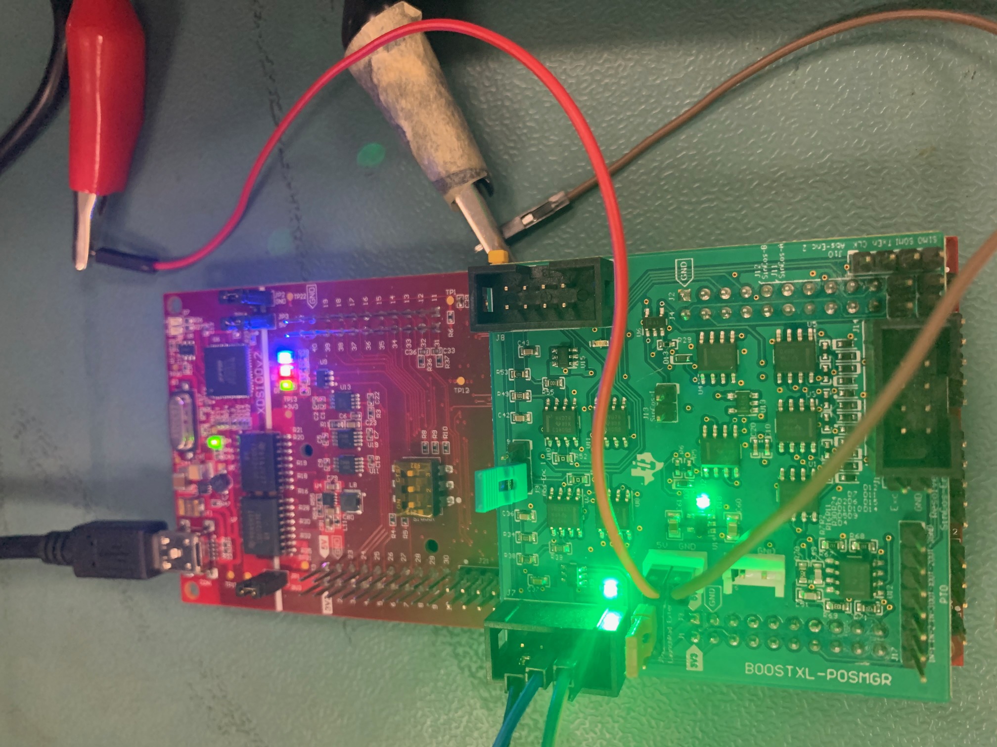
I download the tformat_f28379x_boostxl_posmgr_site2 project into my launchpad.

however, when I spin my encoder, there is nothing changed in expression window.

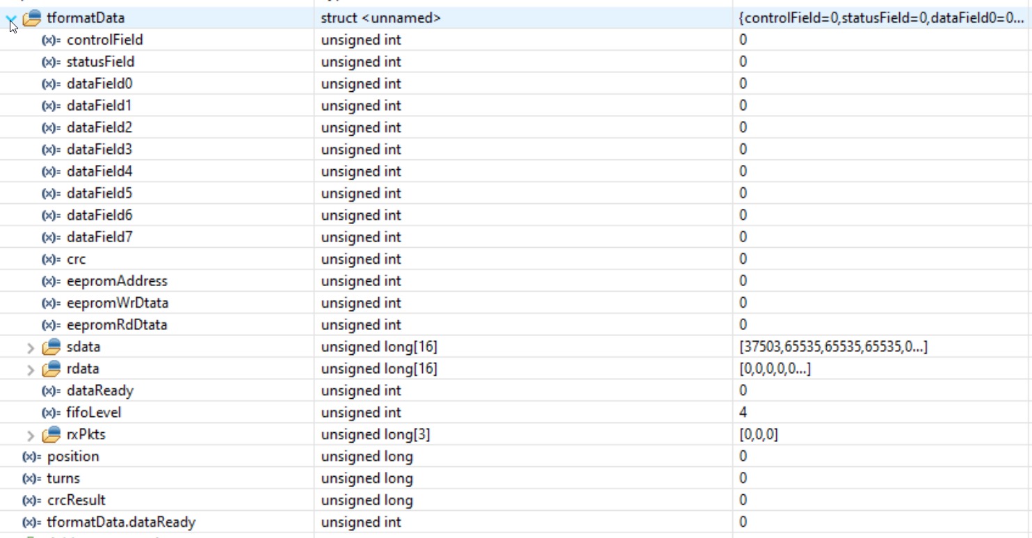
and when I click suspend, it stops at this line always.

could you kindly point out my errors?

And I test two encoders, the phenomens are same, part number:

TS5700N8421SNA00071

TS5720N8401SNA00323

BR

EMMA

  • Hi Emma,

    Our expert will reply to you ASAP. Thanks.

    Regards,

    Chen

  • Hi Emma, 

    Can you check the output from the C2000 on a scope?  Check the TXen the DATA_OUT and the clock line.  

    The data stream should be 2.5MHz rate (pulse width 400ns) for t-format.

    Best Regards

    Lori

  • Hi Lori,

    No, I did not see any signal from the pins.

    should I enable some modules before the test?

    in the guide, it tells everything is set in the code.

    BR

    Emma

  • Emma,

    Make sure to check the pins configured in the source code.  I noticed the documentation figure has the wrong pins. 

    Refer to the function void tformat_setupGPIO(void)

    In the file tformat.c

    Regards

    Lori

  • Lori,

    I go through the function tformat_setupGPIO and then figure out the new GPIO mapping.

    However, I still can not find any pulse, only 0V change to 3.3V when I begin to run the code.

    so I want to know where I did wrong?

    does I should connect GPIO7 to GPIO65 externally?

    does the board need a large current? and I should use a thicker voltage supply wire?

    or I should add the 15V voltage to the doughter board? 

    BR

    Emma

  • Emma,

    Did you try without the boosterpack connected?  It would be good to see if the C28x is accessing pins correctly without the booster pack first.  

    Without the boosterpack you will need to connect pins GPIO7 and GPIO65.  There should be activity on DATA_OUT, TXen and the clock output from the CLB.  Since there will not be an encoder to answer, there will only be one packet coming out of the C28x so set the scope up to trigger and then run the C28x code. 

    Once this works then you can add the boosterpack and try.  In this case the boosterpack will connect GPIO7 and GPIO65 for you. 

    The launchpad can supply 5v - if this works for your encoder you can try supplying the voltage to the encoder from the boosterpack connector. If that does not work, then I suggest supplying it to the encoder separately making sure the voltage supply doesn't current limit. 

    Emma Wang said:
    does the board need a large current? and I should use a thicker voltage supply wire?

      The board itself should be fine - the transceiver needs power.  Check that the LED near the encoder connector is lit.

    Emma Wang said:
    or I should add the 15V voltage to the doughter board? 

    The boosterpack doesn't need 15V. Check to see what the encoder you are using requires and you may need to supply it separately.