This thread has been locked.

If you have a related question, please click the "Ask a related question" button in the top right corner. The newly created question will be automatically linked to this question.

TMS320F28335: Serial communication with the TMS320F28335 via USB

Part Number: TMS320F28335
Other Parts Discussed in Thread: C2000WARE

Hello.


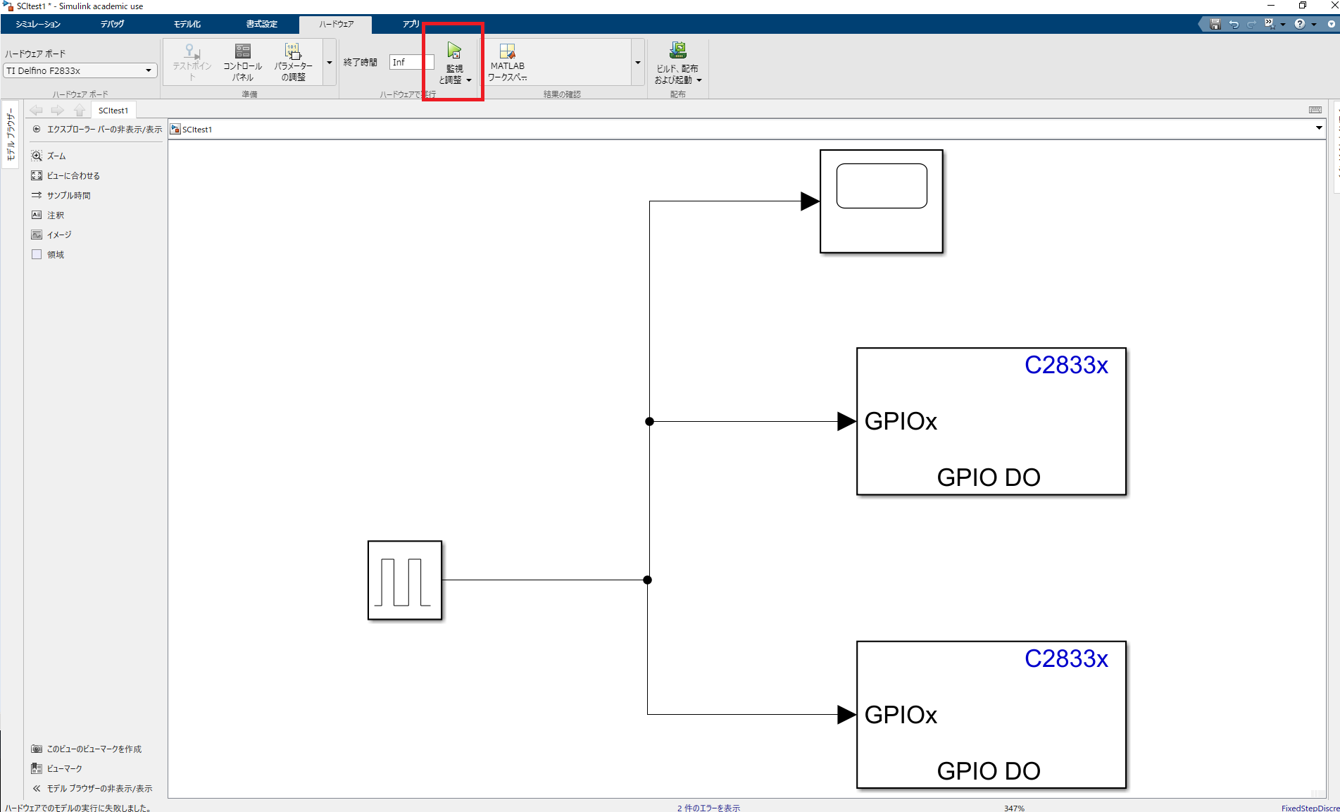
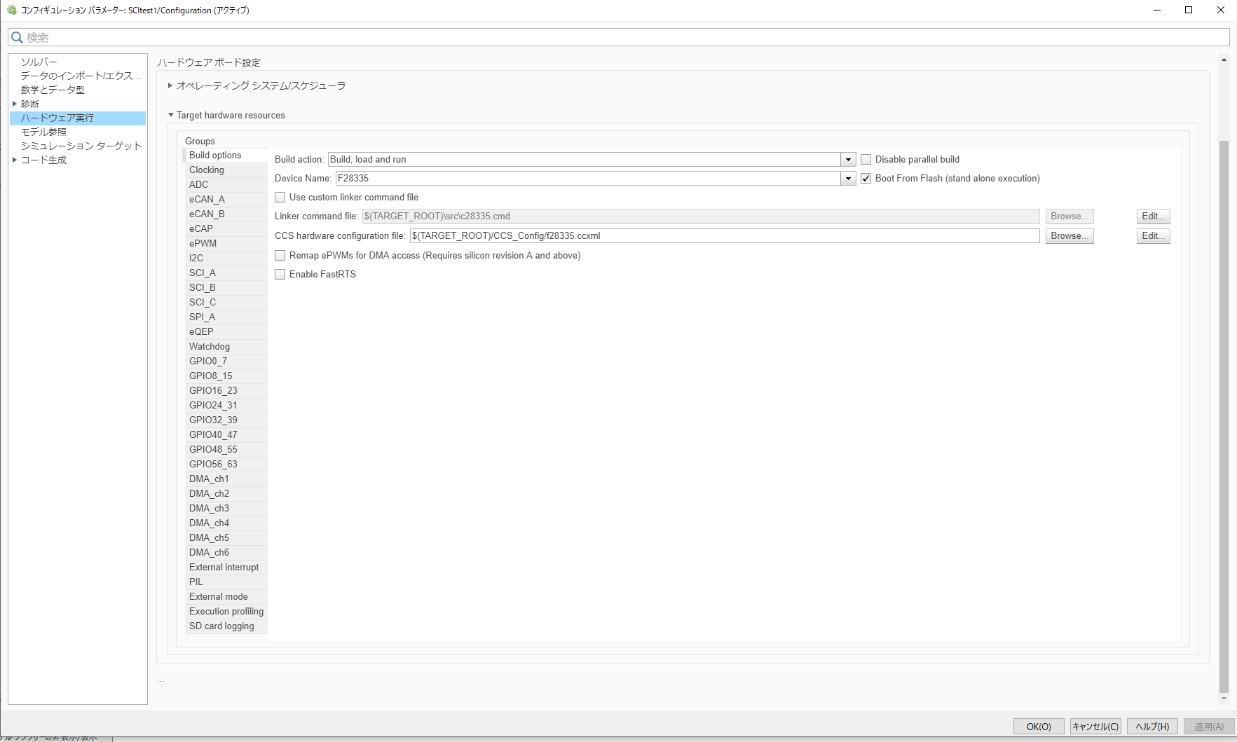
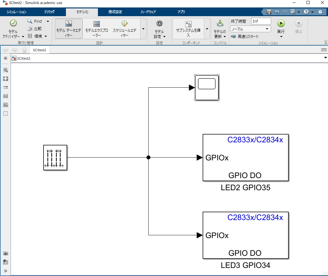
I’m trying to use Simulink for serial communication.

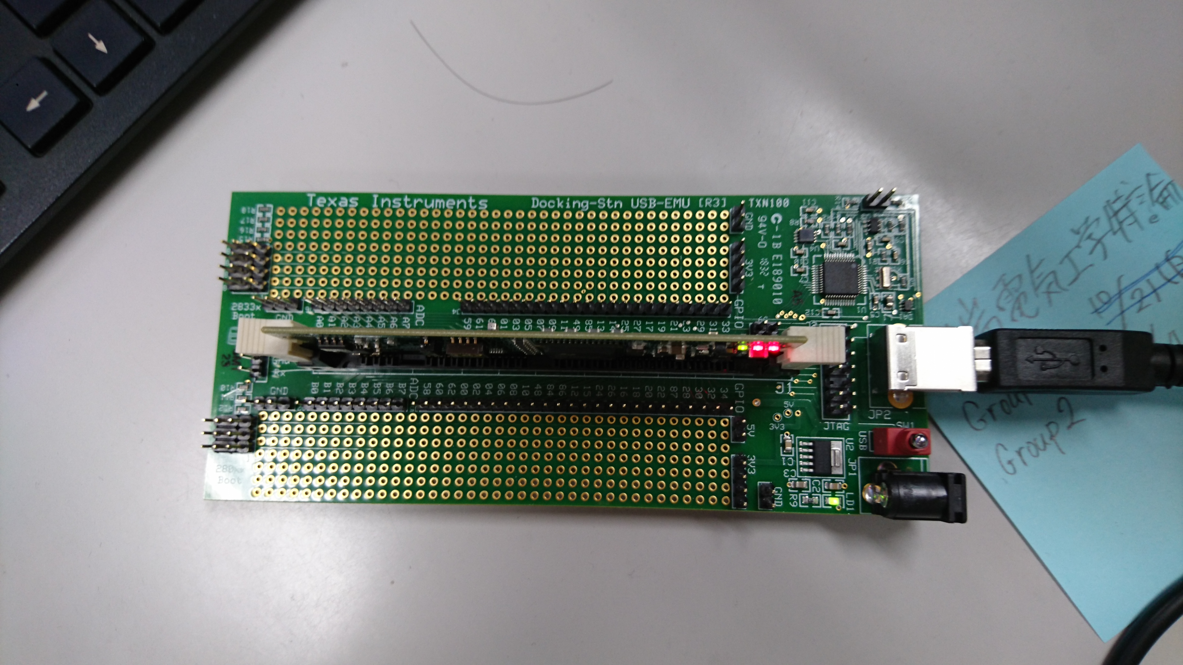
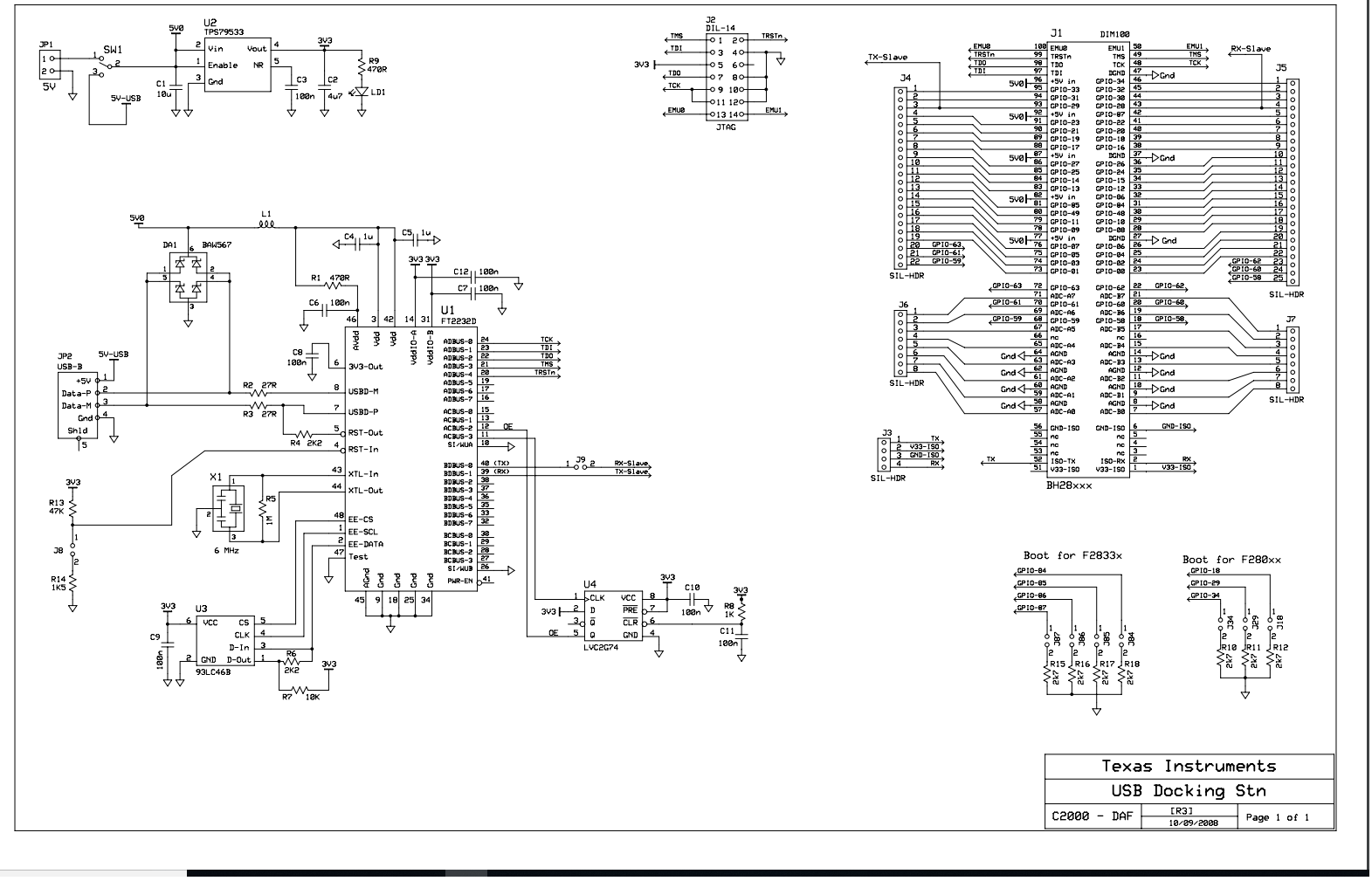
I use ‘TMS320F28335’ and ‘USB Docking Stn’.

Build is successful and the LEDs blink as programmed.

However, the serial communication fails. So, it is not possible to monitor the ‘scope’ in real time.

If I can resolve this, I can try next stage, so I would like to hear your solution.


I have proceeded with the following pages, but I can't!

https://e2e.ti.com/support/microcontrollers/c2000/f/171/t/869091?CCS-TMDSDOCK28335-How-to-connect-SCI-USB-UART-bridge-TMDSDOCK28335-docking-station-and-F28069-ControlCard

https://e2e.ti.com/support/microcontrollers/c2000/f/171/p/569793/2320123#2320123
     https://e2e.ti.com/support/microcontrollers/c2000/f/171/t/665480
  

Thanks,

  • Hi user6037567,

    Please have a look at these instructions on MathWorks' site for some debugging notes.

    Best,

    John

  • Hello, John.

    Thank you for your reply.


    I've tried your advice for a few days, but I can't solve it.

    I would like you to tell me a little more about these instructions on MathWorks' site for some debugging notes.


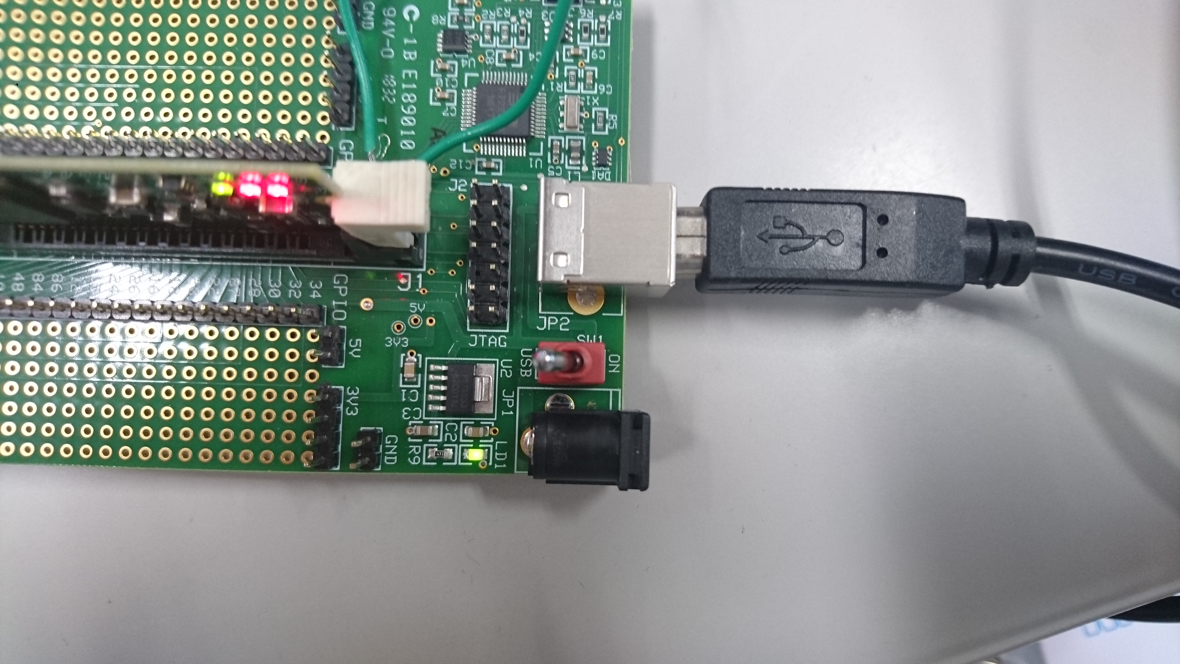
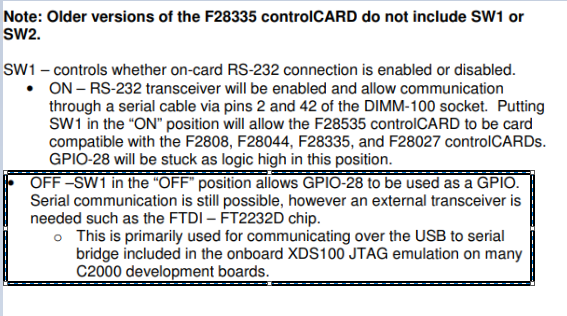
    ・The DIP switch (SW1) on the control card is in off position to enable the serial emulation using the FTDI chip.

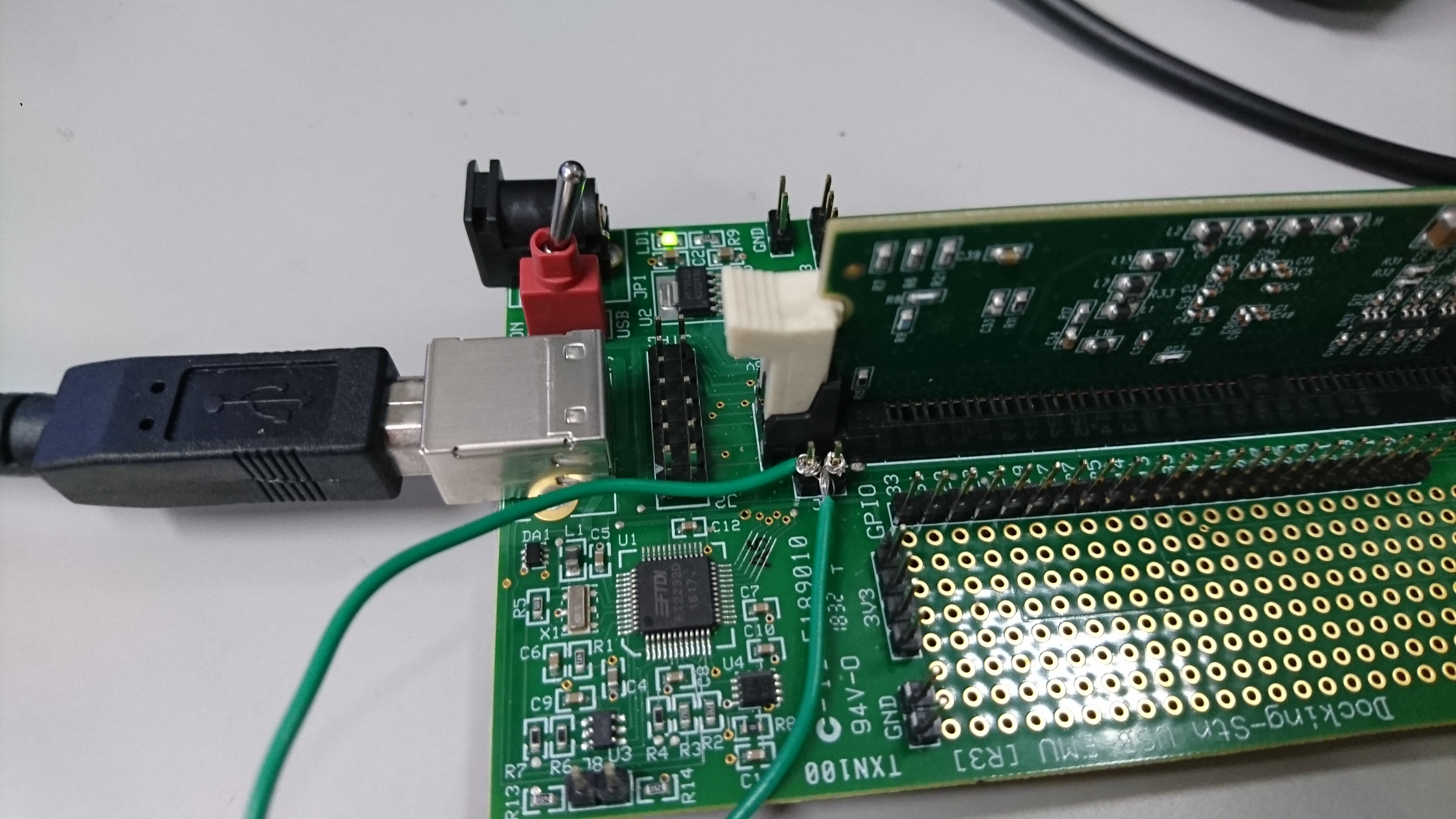
     Q1. Is the off position correct on the photo?

     Q2. Please tell me how to check if serial emulation is valid.


    ・The CCS tool is closed before running the program in external mode. You can use a tool such as PuTTY to test the basic working of Rx and Tx before trying the external mode.

     Q3. Please tell me how to test the basic working of Rx and Tx using PuTTY.

       I can display up to the terminal window on PuTTY.


    Thanks.

  • The DIP switch is in the correct position, use both the onboard XDS100 emulator and its UART backchannel.

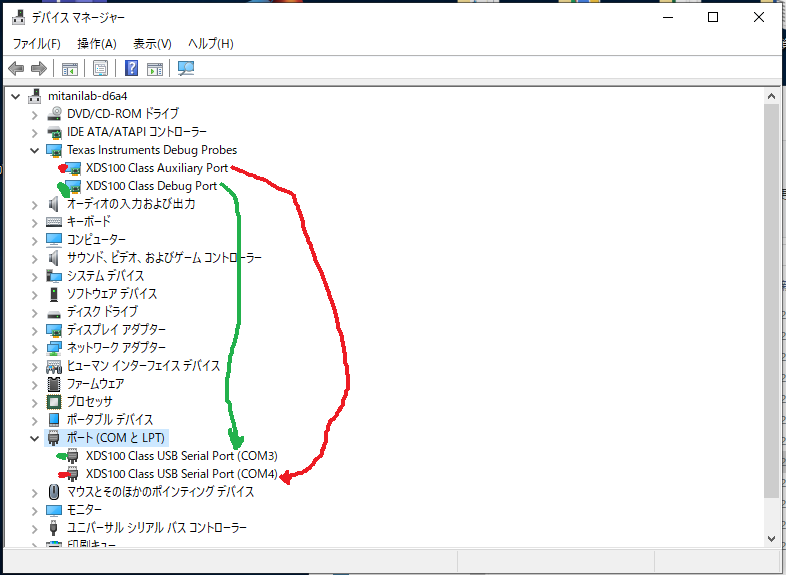
    If you open your Windows Device manager, you should see 2 XDS100 enumerated, one is for the emulator(usually "A) the other supports UART comms between the PC host/MCU.

    I would connect to the device with CCS, then build and load and run the echoback example located here in C2000Ware

    C:\ti\c2000\C2000Ware_3_01_00_00\device_support\f2833x\examples\sci_echoback\

    Baud Rate is 9600 by default, then connect to the port defined in the Windows Device manager.  If all this works then the MW tools should be able to communicate with the device as well.

    If any step does not work, please reply back with that step and we can debug further.

    Best,
    Matthew

  • Hello, Matthew.

    Thank you for your reply.


    I'm not familiar with CCS, so I'm having problems.

    I think I've debugged, but nothing has changed since then.


    I would like you to teach me the procedure after that.

    In addition, I have a question.

    If this succeeds, does it mean that Simulink can also perform serial communication?


     I'm sorry I couldn't reply because I've been busy lately.


    Thanks.

  • Yes, this is correct.  You will need to run the program(green arrow in CCS).  Once this is done you'll need to use Hyperterm(or any PC Host UART comms) to connect to the comm port listed in Windows device manager for the 2nd XDS100v2 channel.  Once you do this you should see any character you type get echo'd back to the hyperterm console.

    I think I mis-spoke on the default baud rate, please check the comments section in the c file you are showing, it will give the correct default baud(I think it may be 116xxxbps vs 9600)

    If this works then we know the comms channel/connection is good and MW should also work.  If it does not, then we need to debug more to get the channel active.

    Best,

    Matthew

  • Hello, Matthew.

    Thank you for your precise and kind reply.


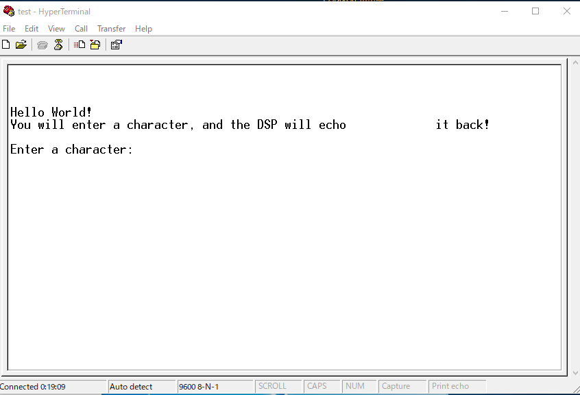
    When I ran the program and connected to COM4, I got this display.


    I think it's a very easy question.

    I can't enter characters, what should I do?

    I feel that success is near.


    I have another question I noticed.

    Do I need to separate the debug port and the serial communication port?

    This is because connecting to COM3 will fail.

    COM3 corresponds to the debug port (green) and COM4 corresponds to the auxiliary port (red).

    Thanks

  • Yes, we are now connected to the device via the UART(SCI) port on the C2000 and the back channel of the XDS100v2.  COM3 is dedicated to the debug/JTAG connection to the device and COM4 is the UART port as you have noticed.

    Since you have seen this dialogue on the hyperterm it means that the C2000 has transmitted successfully this message out to the PC(this should mean that the baud rate is correct as well).  I'm not sure why you aren't able to enter characters, but I think at this point we've established that the channel/connection is good.

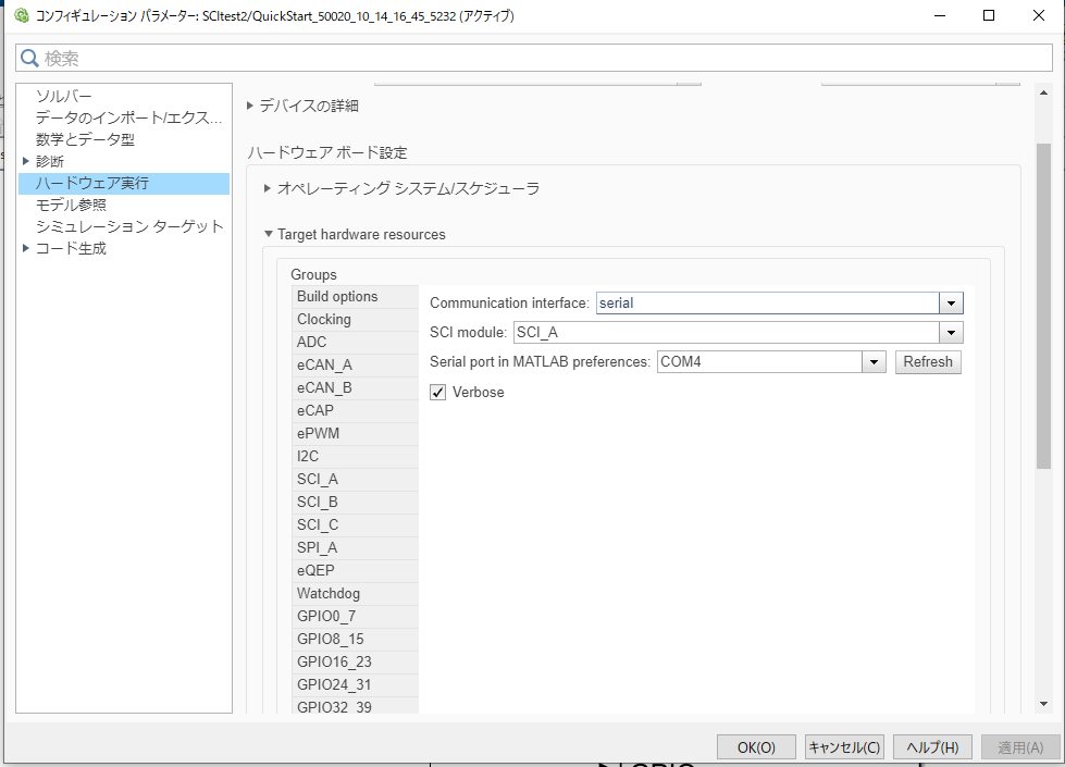
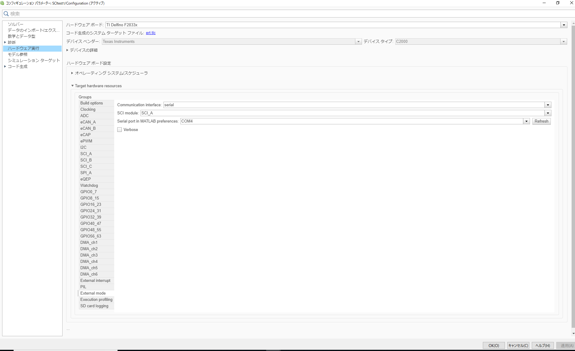
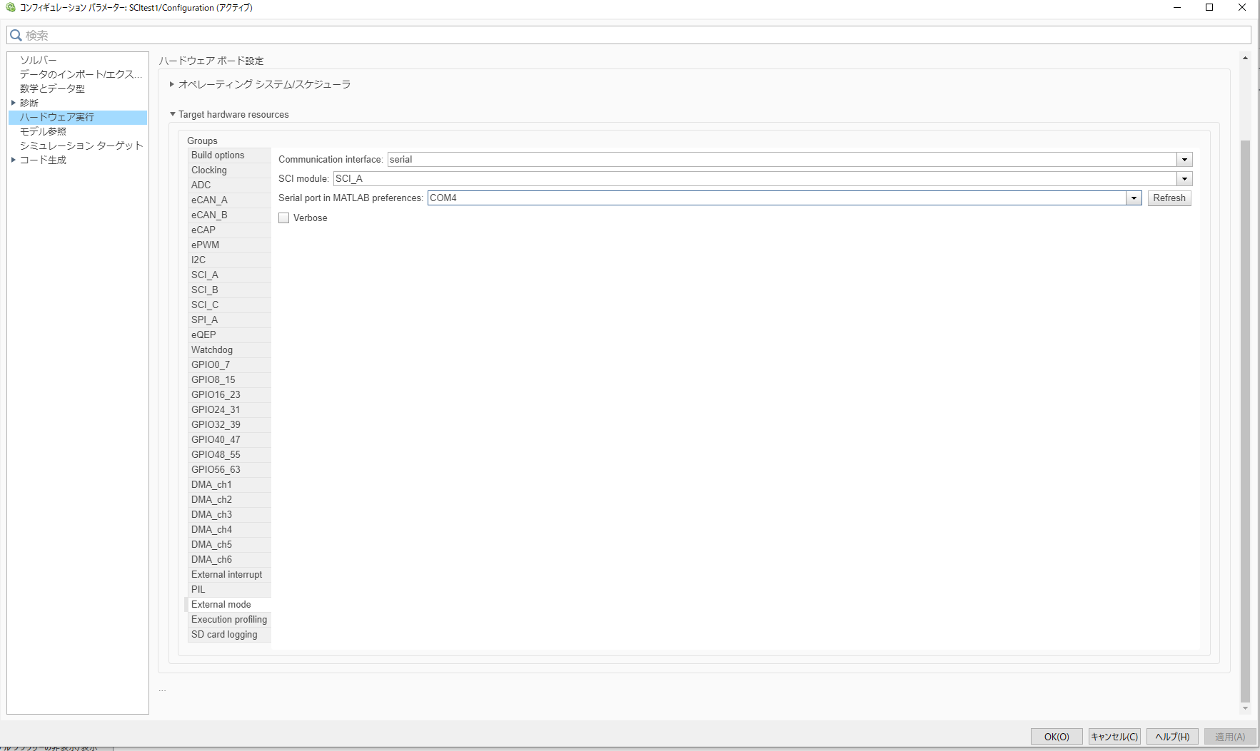
    Is it possible to go back to MATLAB/Simulink and specify that COM4 is the comm channel?  I'm assuming there is a different place to select the emulator/XDS100v2.  For that you should NOT need to specify COM3.

    Best,
    Matthew

  • Hello, Matthew.

    Thank you for your precise and kind reply.


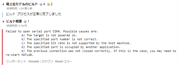
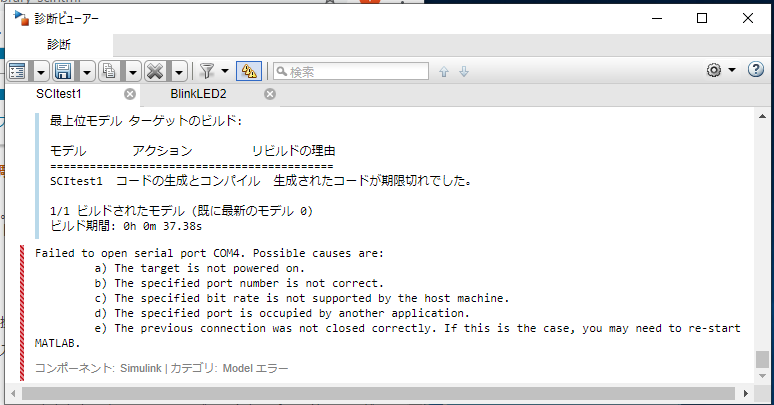
    Thanks to you, I'm getting to know how it works, but the communication fails on Simulink.

    A possible cause would be (d) or (e).

    Or, I may not be able to separate the debug and serial ports.

    The goal is to monitor the display as a first step.

    I'd be happy to get some advice.


    Thanks

  • I checked the DS of this device, and there are only 1 set of GPIOs(GPIO35/36) that SCIA can use for its TX/RX.  Can you make sure that you have closed the hyperterm application before trying to comm with the Simulink/Matlab? 

    Also, I noticed there were 2 green wires in your earlier post; the SCI comms will be handled over the same USB connection that is providing the JTAG link; I wanted to make sure you didn't hand wire the SCI signals out to the headers you have shown.  There is no need for extra connection to achieve the SCI connections on this board.

    Best,

    Matthew

  • Hello, Matthew.

    Thank you for your precise and kind reply.


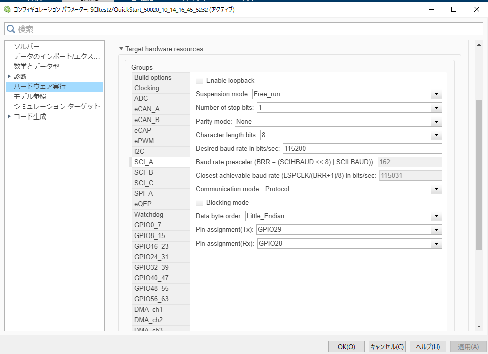
    I specified GPIO as 35 and 36, confirmed that hyperterm was also closed, and ran Monitor and Tune, but it seems that I could not connect.


          Thanks

  • I'm going to ask the MW team to take another look here, we've established that the UART channel is working since you can see the message in hyperterm.  I'm not certain if the issue is that you can't write across the bus is the same issue in Simulink.

    Best,

    Matthew

  • Hi,

    You may want to check the SW1 switch position:

    Please contact MathWorks Support if the problem persists.

    Support - MATLAB & Simulink (mathworks.com)

  • Hello.

    If it is set to the ON position, power will not be supplied to the DSP. It also does not respond to Device Manager.
    Do you need another power supply?

    I also asked a question on the MW forum.

    jp.mathworks.com/.../658288-tms320f28335-serial-communication-with-the-tms320f28335-via-usb

    Thank you

  • Hi,

    Matt is out of office this week due to US holidays. He will get back to you next week by Dec 1st. Sincere apology for inconvenience.

  • Hi

    Thank you everyone.
    I want someone to solve this as soon as possible.


    e2e.ti.com/.../959353

    Thanks

  • Just wanted to make sure, you posted another question on same issue or it is another issue?

    In that ticket, it is mentioned that issue started happening after changing oscillator. I have requested one of our colleague to take a look at the issue.

  • Hi.

    It is same issue.

    I'm not sure if the oscillator is the cause.

    Thanks.

  • As the target connectivity issue is supported on other thread, should we close this thread. 

  • I will only address the issue of serial communication here.
    I apologize for blurring of the issue due to the sudden panic