This thread has been locked.

If you have a related question, please click the "Ask a related question" button in the top right corner. The newly created question will be automatically linked to this question.

CCS/TMDSHVMTRINSPIN: C2000 Instaspin_Universal GUI

Part Number: TMDSHVMTRINSPIN
Other Parts Discussed in Thread: TMDSADAP180TO100, TMS320F280049C, , C2000WARE, TMDXIDDK379D, HVPMSMMTR, TMDSCNCD280049C

Tool/software: Code Composer Studio

Hello team,

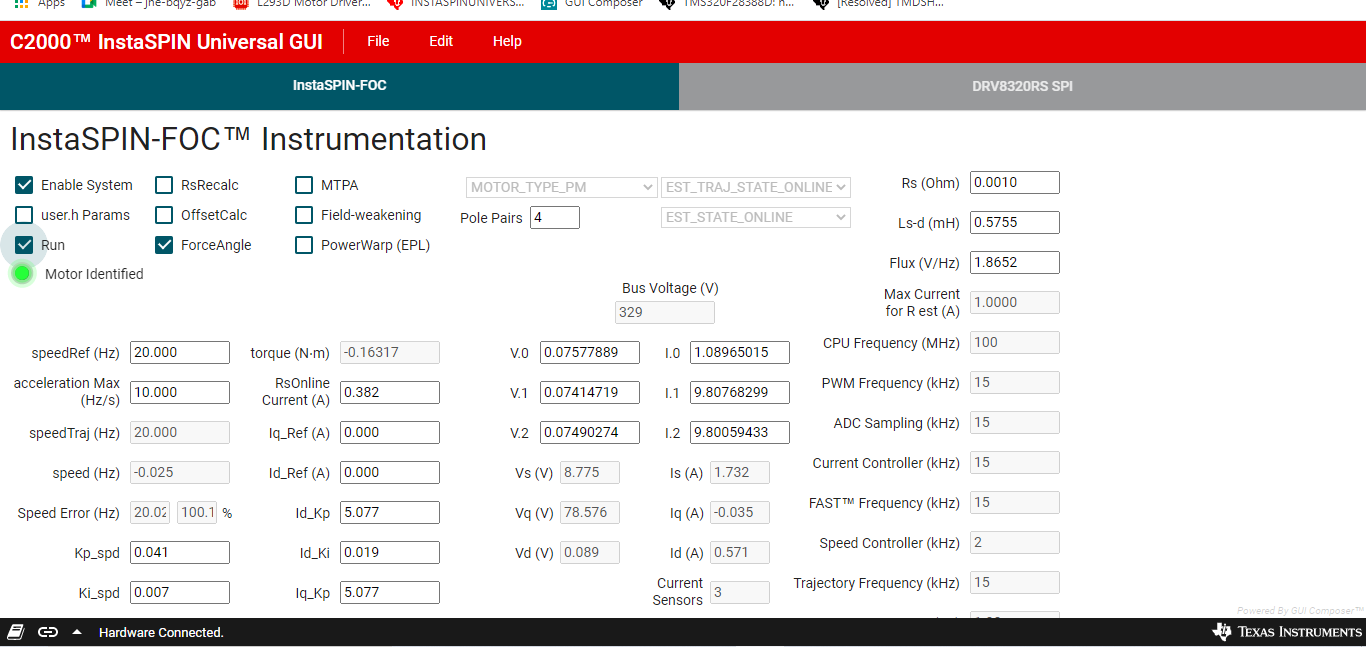
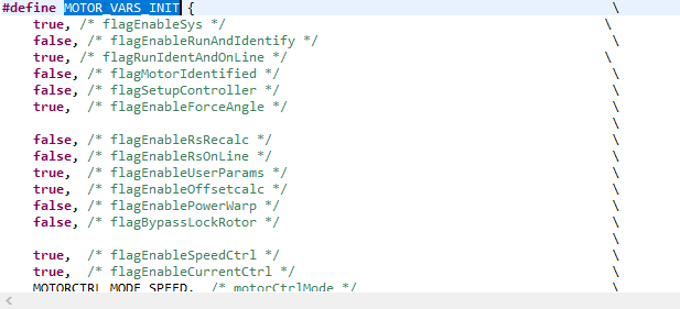
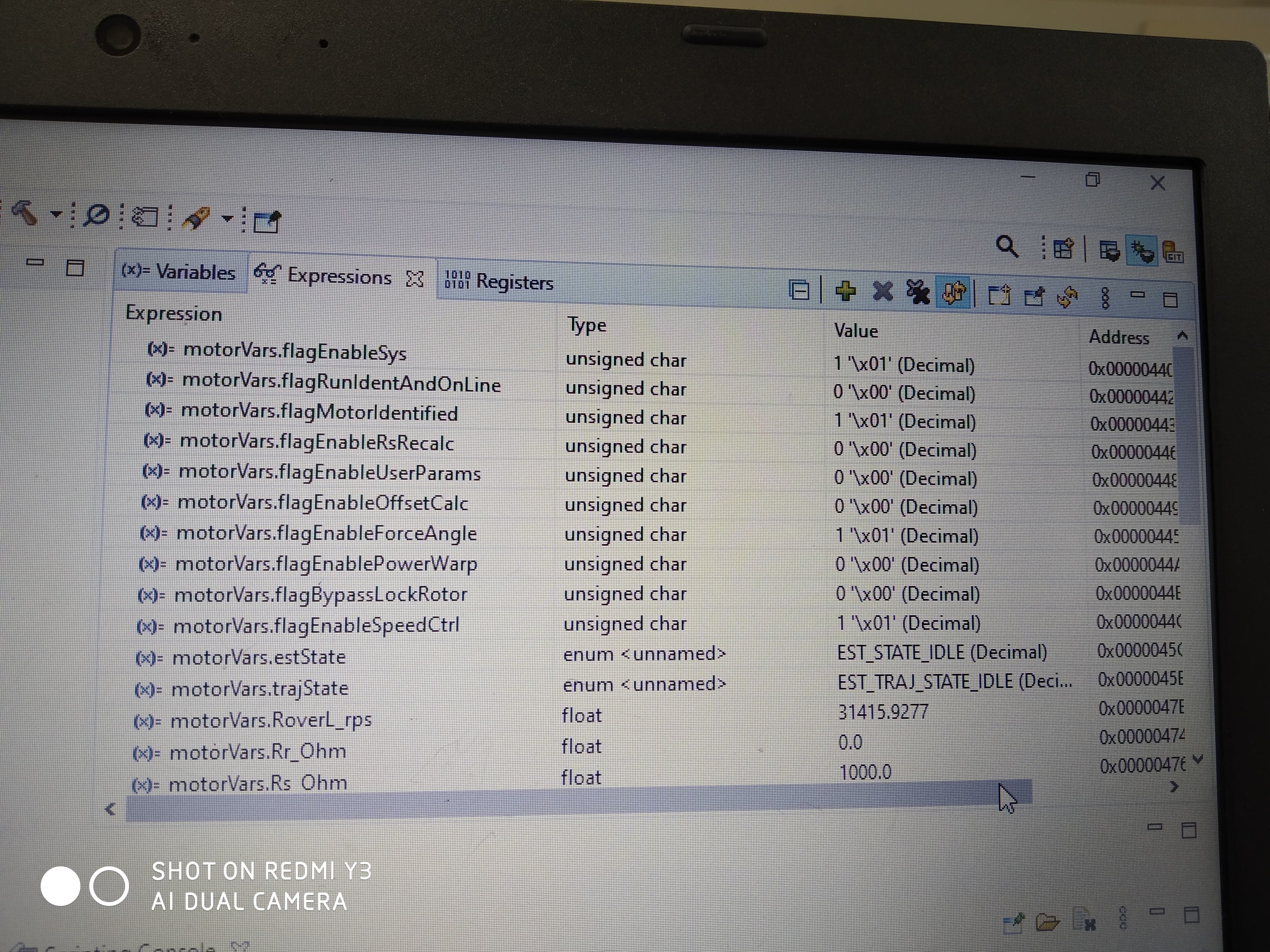
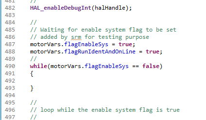
we recently purchased TMDSHVMTRINSPIN development kit, TMS320F280049C control card  and TMDSADAP180TO100, we need to load the the example(lab5) which is available "C:\ti\c2000\C2000Ware_MotorControl_SDK_3_00_01_00\solutions\tmdshvmtrinspin\f28004x\ccs\sensorless_foc " , i put the jumper settings of TMDSHVMTRINSPIN as mentioned in hardware guide,

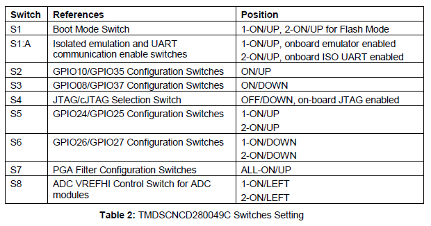
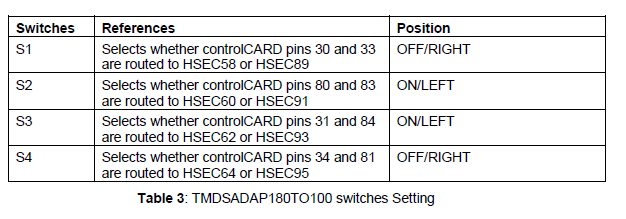
and i put the control card and docking station switches settings as  below, when i open the c2000 instaspin gui i get the below error, what are the steps i need to take to avoid this poblem?

i get the below error "

" Hardware not Connected.Failed to connect to TMS320F280049C device: Please unplug your hardware, then plug it back in and try again."

thank you

  • The GUI is designed to work with the F28004x LaunchPad which uses a different type of debug probe from the controlCARD (XDS110 vs XDS100). Have you imported the GUI into the GUI Composer editor and updated the project properties to use the XDS100? Have you replaced the default .out with that of the TMDSHVMTRINSPIN version of the lab?

    Whitney

  • Hi thanks for the reply ,

    1.i didn't import the gui into the gui composer, i don't know how to to this, can you please provide steps for this?

    2. I update the project properties in code composer studio (CCS_V_10), I change the target configuration to xds100 and tms320f280049c.

    3. After changing the target configuration I rebuild the project and i put this  . Out file in this folder "Guicomposer/ runtime/ c2000 instaspin universal gui/ target  ".

    4. I do all these for TMDSHVMTRINSPIN  version lab only.

    Thank you

  • When you find the GUI in dev.ti.com/gallery there should be some icons below the GUI description. When you hover over them, you'll see one is labeled "Import to GUI Composer"--click that one and it will take you to the GC editor. You can then go into Project -> Properties and click the NEXT button until you see where you can edit the connection settings and upload a new lab executable.

    Whitney

  • Hi thanks for the reply, i followed the steps provided by you, i got the below result, my hardware is connected. i didn't apply ant AC voltage and i didn't connect motor, now i am going to apply AC and connect motor, but i have some doubts,

    1. when i apply AC  after connected to GUI or before connected to GUI ?

    2. when i connect motor to the kit?

    i got the below result

    thank you

  • Please take a look at the user guides in the folder below, try to use an isolated AC source or isolation transformer for the AC power supply of the high-voltage kit. 

    C:\ti\c2000\C2000Ware_MotorControl_SDK_3_00_01_00\solutions\tmdshvmtrinspin\docs

    1. Connect the motor before applying the AC power to the kit.

    2. Connect the GUI and load the program before applying the AC power to the kit.

    3. Check the "Enable System" and "Run" after connecting the motor and applying the AC power.

    Recommend you follow the instaSPIN lab guide below to run these labs with CCS if you are not using the default motor for the labs and kit.

    MotorControl SDK InstaSPIN Lab Guide.pdf

    C:\ti\c2000\C2000Ware_MotorControl_SDK_3_00_01_00\solutions\common\sensorless_foc\docs\labs

  • hi thanks for the reply,

    There is no  sensor based example for TMS320F280049c +  TMDSHVMTRINSPIN development kit, i searched for sensor based example code in the below path " C:\ti\c2000\C2000Ware_MotorControl_SDK_3_00_01_00\solutions\tmdshvmtrinspin\f28004x\ccs " , can you please suggest me whare the senor based example is located. i found only sensor less example.

    thank you

  • There is only sensorless instaSPIN-FOC for the High Voltage kit in motorControlSK.

    The sensored-FOC is not based on the instaSPIN technique, it's typical sensored-FOC with an encoder on IDDK that can be found in the folder below in motorControlSDK, and it can be supported by the GUI also.

    C:\ti\c2000\C2000Ware_MotorControl_SDK_3_00_01_00\solutions\tmdxiddk379d\f28004x

  • hello team,

    i want to run the pmsm motor by using  TMDSHVMTRINSPIN  +tms320f280049c,i followed the steps provided by you, now i am going to connect the motor and try to run motor, am i going in correct way? if there is any mistake can you please suggest me. can anyone please check my above posts and suggest me.

    thank you

  • You might follow the hardware guide or the steps mentioned above to connect the power supply and motor, to tun the related labs in motorControlSK.

    Recommend you use an isolation transformer for the computer and any other instruments for the kit. And use an AC source for the power supply of the High voltage kit if possible.

  • Hi thanks for the reply, i followed the hardware guide, i put jumper settings as per the hv kit guide, and i am using isolation transformer. Now I connect motor, can I proceed with the steps  mentioned above?

    Thank you

  • Please take a look at the hard guide in the folder below, to make sure that the switches on controlCard are correct as well.

  • Thanks for the reply, I put the switches settings as per the gudie on control card...i falsh the is_motor id 5 example code  on tms320f280049c  control card, and i update user.h file also..

    Thank you

  • Yes, you may go ahead. Let's know if have any further questions.

  • Hi, thanks for the reply,

    i connect the motor and apply the AC as the steps provided by you, my motor was identified correctly, after identifying the motor we go to  check RUN button, in GUI, but my motor is not spinning ,i have attached the GUI screen please find it, and help me to run the motor.

    thank you

  • Hi, we are using pmsm motor with the below parameters, motor was identified  in the GUI, when we try to run the motor, there is no movement in motor,can you please support us to run the motor.

    #if (USER_MOTOR == Estun_EMJ_04APB22_A)
    #define USER_MOTOR_TYPE MOTOR_TYPE_PM
    #define USER_MOTOR_NUM_POLE_PAIRS (4)
    #define USER_MOTOR_Rr_Ohm (0.0)
    #define USER_MOTOR_Rs_Ohm (2.26793718)
    #define USER_MOTOR_Ls_d_H (0.00808008015)
    #define USER_MOTOR_Ls_q_H (0.00808008015)
    #define USER_MOTOR_RATED_FLUX_VpHz (0.007036026)
    #define USER_MOTOR_MAGNETIZING_CURRENT_A (NULL)
    #define USER_MOTOR_RES_EST_CURRENT_A (1.0)
    #define USER_MOTOR_IND_EST_CURRENT_A (-1.0)
    #define USER_MOTOR_MAX_CURRENT_A (3.80)
    #define USER_MOTOR_FLUX_EXC_FREQ_Hz (20.0)
    #define USER_MOTOR_NUM_ENC_SLOTS (2500.0)
    #define USER_MOTOR_INERTIA_Kgm2 (3.10002e-05)

    #define USER_MOTOR_FREQ_MIN_HZ (5.0) // Hz
    #define USER_MOTOR_FREQ_MAX_HZ (400.0) // Hz

    #define USER_MOTOR_FREQ_LOW_HZ (10.0) // Hz
    #define USER_MOTOR_FREQ_HIGH_HZ (200.0) // Hz
    #define USER_MOTOR_VOLT_MIN_V (30.0) // Volt
    #define USER_MOTOR_VOLT_MAX_V (200.0)

    thank you

  • Please follow the InstaSPIN lab guide and the GUI guide, you should use the lab07 to run the motor with the identified motor parameters.

    Recommend you run the related labs with CCS following the lab guide if you want to run your own motor.

  • Hi,

    Just to inform, we are using 
    HVPMSMMTR. To recap my situation: My hardware is:  TMDSHVMTRINSPIN (HV kit) +  TMDSCNCD280049C (control card) + HVPMSMMTR (motor) + TMDSADAP180TO100 (100 to 180 adapter)..

    Step 1: In CCS10,I import project " is07_speed_control ": I have selected motor "Estun_EMJ_04APB22_A". Project saved and build - I have got app prog.out file
    Step 2: In "C2000Ware_MotorControlSDK_InstaSPIN_GUI: app prog.out file is loaded; after loading  .out file we observe that LED(D3) on control card is starts blinking.
    In the following screen (Instaspin FOC Instrumentation): "Motor identified" is highlighted & 
    DCBUS voltage is shown as 0V (though HVKIT AC is off and we click enable system on GUI).
    Step 3: Now 
    AC to HVKIT is turned on.  DCBUS voltage is shown as 330V.

    Observations: On RUN, motor doesn't respond. We measured Motor Winding's resistance = 2.2ohms (as per data sheet)

    1. We followed "quick start guide" instructions line by line for Jumper settings of HV Kit, Control card and 180-100 adapter.
    2. We followed "GUI guide" 
    instructions line by line
    3. 
    We followed "Lab guide" instructions line by line for is07_speed_control .

    Observations: We also changed HVPMSMMTR parameters  like Max Current to 6A, Start current to 9A. But Motor still doesn't rotate.

    Where shall I focus my debugging?


    thank you

  • You might run the lab with CCS to make sure that the motor can spin well first, and then use GUI to run it as you mentioned above.

    Looks like the DC bus voltage is too low in the GUI above, please check if the DC power supply is applied to the kit correctly.

  • Thanks for the reply

  • It will be a fault to disable running the code if you don't apply a correct power supply to the kit.

    You can take a look at the lab guide in the folder of motorControlSDK below.

    MotorControl SDK InstaSPIN Lab Guide.pdf

    C:\ti\c2000\C2000Ware_MotorControl_SDK_3_00_01_00\solutions\common\sensorless_foc\docs\labs

  • thanks for the reply, i successfully spin my motor with different speeds

  • I have completed Lab 1 to 5 and tested various parameters of motor using CCS_v10, Lab is05_motor_id, PC based "C2000Ware_MotorControlSDK_InstaSPIN_GUI " , script " is05_motor_id.js "  , Now we want to spin motor without help of PC based GUI (C2000Ware_MotorControlSDK_InstaSPIN_GUI). I would like to flash the program in the tms320f280049c Control card and disconnect USB Jtag XDS100-V2,I expect the motor to run without help from PC based GUI and Jtag cable.


    Could you please provide suggestions ?

    thank you

  •  There are two build configures, you need to use the "Flash_lib" configuration to run the code from Flash. Right-click on project, select "Build Configurations"->"Set Active"->"1 Flash_lib"

    Please go through the E2E post below. Our Flash expert has put together steps to switch from RAM to Flash and list various steps to debug.

    https://e2e.ti.com/support/microcontrollers/c2000/f/171/t/878674

  • Hi, thanks for the reply, 

    I am able to configure and control the Motor using Lab 1 to 5, PC Based GUI by enabling System and Run button. Once the motor is identified the run button unchecked automatically. To run the motor, I am forced to recheck the Run button again.

    Now I plan to control the motor, but without using “PC based GUI” / click Run button etc. I already completed the below 4 steps. My question is: Will it help if I enable “motorvars. flagRunIdentOnline” flag again to run the motor? If yes, how to enable the same? Or am I missing any other steps than mentioned below?

    1. I go to structure volatile MOTOR_Vars_t motorVars = MOTOR_VARS_INIT; in ccs and I put the flagenable sys=true,and I change the runandonline falg=true as shown below.

    2. I flash the code in control card, i add the java script file to watch window, I enabled the real time debugger in ccs. I get the below result in watch window.

    3. The code stats identifying the motor and motor identified flag is set (watch window as below)

    4.I did the above steps by putting the code in flash lib.

    thank you

  • Add the following codes before the "while(motorVars.flagEnableSys == false)" in main file.

    motorVars.flagEnableSys = true;
    motorVars.flagRunIdentAndOnLine = true;

  • Hi thanks for the reply

    Step1:  I added the below code lines in main file

    Step 2:  “ motorVars.flagEnableSys = true   , motorVars.flagRunIdentAndOnLine = true “; shown in below image

    Observation: AC is on, Motor connected, but Motor is not spinning. From the GUI (Screen shots as below / attached) - It looks it is waiting for ‘Run’ button ‘click equivalent’….

    Trial: So I tried to set in code 

    motorVars.flagRunIdentAndOnLine=true

    What else is missing in my sequence?

  • Please use lab07 with the identified motor parameters by lab05 to spin the motor.

    It seems like you didn't apply the bus power supply on the kit.

    Please take a look at the GUI guide and lab guide to run the lab, which has a very clear instruction to use the GUI or CCS to run a lab as mentioned before.

    MotorControl SDK InstaSPIN Lab Guide at \ti\c2000\C2000Ware_MotorControl_SDK_<version>\solutions\common\sensorless_foc\docs\labs

    gui_quick_start_guide.pdf and hardware_getting_started_guide.pdf at \ti\c2000\C2000Ware_MotorControl_SDK_3_00_01_00\solutions\common\sensorless_foc\docs

  • Hi thanks for the reply,

    I gone through lab07 example with identified motor parameters, also applied AC supply to hv-kit,I have attached the results in below images.

    I gone through GUI guide and lab guide, in those guides the instructions are about to run the motor with GUI or ccs, but my main aim is to spin the motor without GUI or CCS(real time). How do i did this?

    Thank you

  • As mentioned above, use the "Flash_lib" build configuration, and set the enable flag and reference speed before the man loop. And set the right switch on controlCard to enable the device to boot from flash as the link below.

    https://e2e.ti.com/support/microcontrollers/c2000/f/171/t/878674

  • Hi thanks for the reply,

    We made the following modifications, to get the motor running without user interaction (or GUI) and from internal flash of controller. Please review these steps and confirm. After your confirmation, we will test it on the real hardware.

    1. Before entering the first while(), we have set the following two flags and initialized one new 16-bit counter, before starting the initial motor identification process:
      1. a.      motorVars.flagEnableSys= true;
      2. motorVars.flagRunIdentAndOnLine = true;
    2. When “motorVars.flagMotIdentified == true” condition is true, we start incrementing the 16-bit counter. The time base is taken from the 1ms Time Base (tick).
    3. After this 10sec (10000 x 1ms) delay, again we set the “motorVars.flagRunIdentAndOnLine = true” to continue the motor running.

     The code changes are given below. After your confirmation, we will test it on the target hardware (with motor connected and the AC supply given). We will flash it in the controller and run in a standalone mode. Are these modifications correct to safely test with our HV Kit again?


    // ------------ ************* -------------

       gu16TickCounter = 0;

       motorVars.flagEnableSys = true;

       motorVars.flagRunIdentAndOnLine = true;

       while(motorVars.flagEnableSys == false)

       {

        }

       // loop while the enable system flag is true

       while(motorVars.flagEnableSys == true)

       {

           // 1ms time base

            if(HAL_getTimerStatus(halHandle, HAL_CPU_TIMER1))

           {

              motorVars.timerCnt_1ms++;


               HAL_clearTimerFlag(halHandle, HAL_CPU_TIMER1);

               if (motorVars.flagMotorIdentified == true)

               {

                   if (gu16TickCounter > 10000)

                   {

                       motorVars.flagRunIdentAndOnLine = true;

                   }

                   else

                   {

                       gu16TickCounter++;

                   }

               }

    // ------------ ************* -------------

    thank you 

  • That's fine. Go ahead.

  • hi thanks for the reply, i followed all the steps, my motor is running but with low speed, even i changed the reference speed for different values but there is no change in speed of the motor, can you help me to solve this?, 

    thank you

  • How did you set the reference speed since the code is running from flash without using CCS or GUI? Could you please have a detailed description of your questions including the operation steps and the changes in the example lab?

    Any loading on the motor? Did you set the right maximum current according to the motor?

    You might run the motor with the example lab and CCS first, to make sure that you can run the motor as you expect first, and then go to the next step without using CCS.     

  • Hi, thanks for the reply,  i put the code into RAM firstly i ran the motor with GUI ,with reference speed of 20Hz, i didn't do any changes in the example lab05,i followed the gui_quick_start_guide and MotorControl SDK InstaSPIN Lab Guide from the below path, i put the motor parameters as per the data sheet of motor" C:\ti\c2000\C2000Ware_MotorControl_SDK_3_00_01_00\solutions\common\sensorless_foc\docs ", but when i changing the reference speed and acceleration  in GUI there is no change in the speed of the motor,  what i need to do to change the speed of the motor?

    thank you

  • Please re-build the lab07 in CCS with your own motor parameters, and then replace the default .out with that of the TMDSHVMTRINSPIN version of the lab07. Lab05 is for motor identification, it seems like the motor is identifying as you showed above. 

  • Hello team,
    We could identify and run our own ACIM motor using Lab 5 and 7 on HV Kit. And also I can control the speed using lab 07. 
    For calculating kp, ki, as per lab guide: “C:\ti\c2000\C2000Ware_MotorControl_SDK_3_00_01_00\solutions\common\sensorless_foc\docs\labs”
    1. I didn’t understand which sampling frequency (Fs)  is used for bandwidth calculation? (ADC sampling or PWM sampling frequency or ?
             BWc = 2*(pi)*Fs/ 20
  • It's the control frequency that should be equal to ADC sampling and PWM frequency in the reference labs.

    We'd like to close this thread first since it's not a topic as the title of the thread.