This thread has been locked.

If you have a related question, please click the "Ask a related question" button in the top right corner. The newly created question will be automatically linked to this question.

CCS/TMS320F280041C: MCP7940N RTC -C2000

Part Number: TMS320F280041C
Other Parts Discussed in Thread: CC2640

Tool/software: Code Composer Studio

Hi team,

This is regarding the use of MCP7940N IC(RTC-i2C) using 280041C. I've come across  post CCS/CC2640: MCP7940N RTC on I2C with CC2640. I saw the post and I found that I'm having similar issues. I tried different slave addresses like 0X6F and also 0X3C(suggested by ). I would like to understand as how the slave addresses are chosen in this context. 
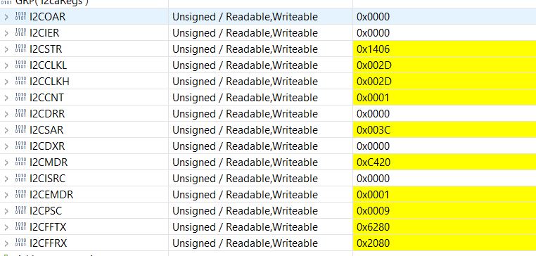
To my knowledge, I did all the read & write as per what's suggested in the datasheet. I would like to know if I'm missing something here. BTW, I use MATLAB Embedded coder for developing firmware. Please find the snapshot of the I2C registers during the debug mode. Few of my concerns are 1. Busy bit is always set. 2. NACK is always set. 3. IRS is always 0. 

Thanks,

Harish K.

  • Harish,

    MCP7940N datasheet should provide the slave address of this device. You cannot chose any arbitrary number. From the DS, it looks its slave address is 0x6F.

    1) Are you I2C pins pulled up? If so, what is the pull-up resistor used?

    2) What is I2C bus capacitance of your I2C network.

    3) Can you probe your I2C pins using I2C logic analyzer?

    Why is busy bit set?

    Busy bit indicate that START condition has been generated and bus is not idle. In I2C master mode, when START condition is generated, busy bit is set.

    Why is NACK set?

    When NACK is set, it means that MCP7940N didn't respond to I2C master commands.

    Why is IRS cleared state?

    I2CMDR.IRS bit is user configurable. In your code, you must be clearing this register. When this IRS bit is cleared, then it means I2C is disabled.

    Regards,

    Manoj

  • Hi Manoj,

    Yes. I understand that the slave address is not arbitrary and that's why I've used 0X6F. The reason that I asked was that one of the posts mentioned 0X3C as slave address here in this forum. So, I was little confused. 

    1. Regarding the pull-up resistors, we used 10k ohms

    2. There are other devices like EEPROM, Temperature sensor & DAC on the same I2C bus. As per our calculation it is less than 400pF. Since the temperature sensor has a maximum clock frequency around 100kHZ, we are operating all the devices at the same frequency. And I was able to program EEPROM & DAC as expected. 

    3. Right now, I couldn't probe the I2C pins since we are not having the MSO/logic analyzer. 

    Is there a way that we can troubleshoot using CCS till we get logic analyzer?

    Thanks,

    Harish K.

  • Harish,

    It is good to know that you were able to communicate to EEPROM, temp sensor, DAC on the same bus.

    Without logic analyzer / MSO, it becomes tricky to debug such issues. But, here is what I would try, we need to first find whether MCP7940N recognizes the when master transmits it address. I would just generate the START condition with MCP7940N (I2CSAR = 0x6F). If I2CSTR.NACK bit gets set, then it mean MCP7940 is not even responding to I2C master. If it acknowledges, then you may be making mistakes sending incorrect MCP7940N I2C command format.

    If your bus capacitance is high around 400pF, I would encourage you replace 10K pull resistors with 1K pull-up resistors.

    Regards,

    Manoj

  • Dear Manoj,

    Once I get my hands on the logic analyzer, I will try & let you know the status here. 

    Thanks,

    Harish K.

  • Okay. Please reply to post when you have further information. Thread status moved to "Waiting for Customer"

    Regards,

    Manoj

  • Dear Manoj,

    Thanks for your patience. Finally, I got the DSO with a logic analyzer and please find below the screenshots.

    I'm writing data and then reading the data. But, the slave isn't acknowledging if I'm not wrong. In another case when I use a do-while loop while reading from the system, the screen shot is shown as below.

    So, please do let me know if you need any details.I2C_RTCC_MCP79410_2910_ert_rtw.zip

    Edit 1 : I was able to read some data from the clock without the NACK bit being set. But, still verifying the authenticity of the data. The reason is that without I was sending data configuring the control byte.

    And when the oscillator bit when is enabled, the NACK bit is being set to 1 and I'm still figuring the reason as why it is set to 1.  Does that mean the oscillator is not functioning?

    Please let me know if you see anything from my inferences. 

    Thanks,

    Harish K.

  • Harish,

    From the oscilloscope snapshot, it looks like MCP7940N is not responding to I2C master. What is puzzling is that you're able to talk to EEPROM, temp sensor, DAC etc without any problem. It is possible that MCP7940N (slave) isn't working.

    Did you try replacing the part (MCP7940N)? Did you try replacing 10K pull-up resistor with 1K pullup resistor.

    Also, what do you mean by "And when the oscillator bit when is enabled" ? What is the oscillator bit and how is it affecting I2C communication? Were you able to receive ACK from MCP7940N atleast once?

    Regards,

    Manoj

  • Dear Manoj,

    Yes. I was able to communicate with the RTC and please find the screenshots below for the same.

    Please find the routine below for configuration routine of the RTC. When I'm implementing the ST bit, the result of the I2CSTR is 1446. But, if I don't write to that particular seconds register(oscillator start bit register) which is having start bit, the result of I2CSTR is 2460 which is exactly what we need. But, it is of no value since it is not the real time. 

    The same issue comes up even when the hours register is being accessed or if a value is being written to. The value of I2CSTR get sets to 1446. And I do have a development board for the same. I even tested on it. But, the results were the same. If I access Hours or seconds register, the slave isn't responding or I2CSTR is 1446.

    So, please let me know.

    Thanks,

    Harish K. 

  • Harish K,

    Your questions are more specific to MCP7940N. I'm not familiar with MCP7940N command sequences. You need to check with Microchip on your observation.

    But, why I2C waveform look triangular? Your first waveform in earlier post did have a proper square waveform.

    Regards,

    Manoj

  • Dear Manoj,

    Thanks for the message. I did solve some of the issues related to the particular query. It was more on the implementation side of it. I too didn't get as why the waveforms were triangular sometimes. Please let me if know.

    Thanks for the response.

    Thanks,

    Harish K.

  • Harish,

    If I were you, I would have a stronger pull-up say 1K on both SCL and SDA lines. Having stronger pull-up will ensure the bus capacitance gets charged sufficiently in short time period. If you have a weaker pull takes longer time to charge I2C bus capacitance which can lead to have sawtooth like waveform like you are observing.

    I2C Bus Pull-Up Resistor Calculation - Texas Instruments

    Regards,

    Manoj