

Dear team:
My customer has a question about Park Transformation.
Hardware: Self designed motor control kit
Software reference: IDDK_PM_Sevor_F2837xD_V2
Level1 and level2 are running normally. But in Level 3, the motor control is not very stable, and the heating is very serious. Then he returned to level2 and found that the DS and QS after Park transformation were not constant values and were changing all the time. He suspected that it was the current acquisition or rotary encoder problem, but he could not find the specific reason.
He input the standard sinusoidal signal into Clarke transform and output 90 phase difference signal, and then input it to park transform. He found that the output d = 0.5, Q almost equals 0 (floating around a very small value).
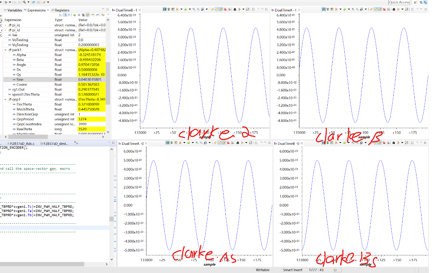
Then he used the current signal collected by himself (as shown in the figure below), and found that the waveform was roughly the same. The main difference was that the amplitude of the actual signal was much larger (not normalized). Except for some burrs, the phase was almost the same. However, it is found that D and Q are not constant after Park transformation, and they change greatly. (clarke.Alpha and clarke.beta are the inputs to the park transform.)

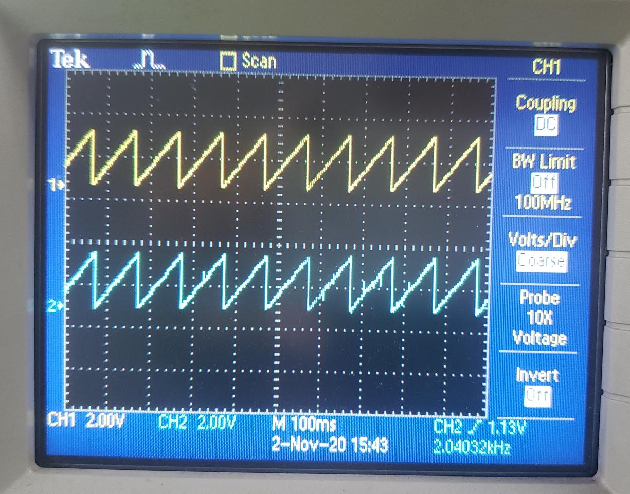
In addition, the following figure shows the signal of encoder. The upper part of the figure is rg1.out, the theoretical value, and the lower side is the electrical angle measured by the encoder. It is found that it is almost the same as page 26 in the manual sprabz0 February 2016, but there are occasional burr. Does this mean that there is no problem with encoder acquisition?
Best Regards
