This thread has been locked.

If you have a related question, please click the "Ask a related question" button in the top right corner. The newly created question will be automatically linked to this question.

CCS/LAUNCHXL-F28379D: CAN reading data into memory/variable

Part Number: LAUNCHXL-F28379D
Other Parts Discussed in Thread: C2000WARE

Tool/software: Code Composer Studio

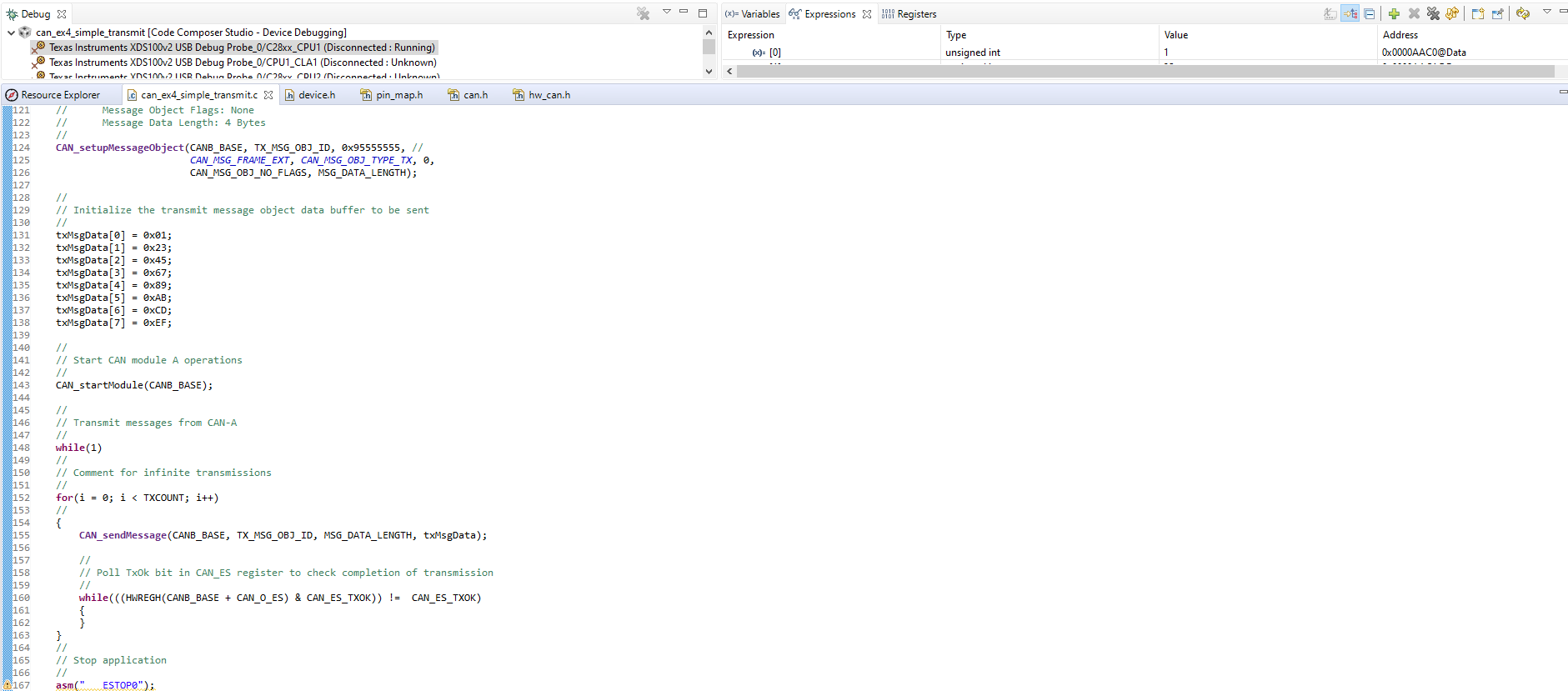
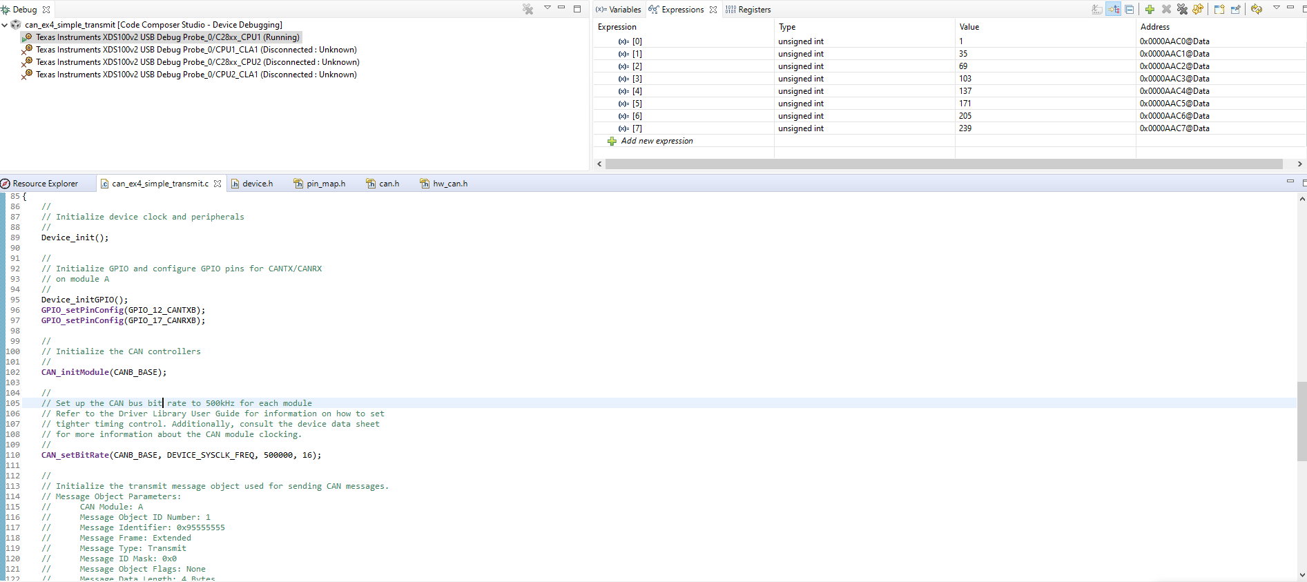
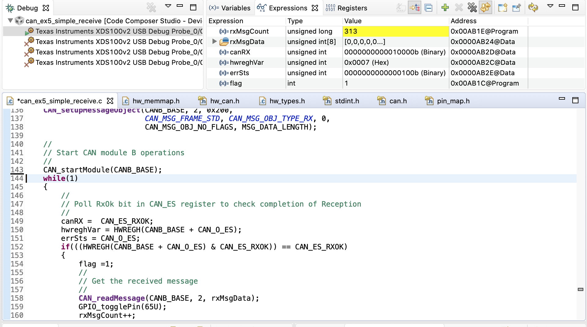
I have two of the LAUNCHXL boards (connected to two different computers) and I am attempting to get them to communicate with each other via CAN. I am using the example code in C2000Ware ex4 and ex5, simple transmit/receive. I have reconfigured the code to use CANB_BASE and GPIO_12_CANTXB and GPIO_17_CANRXB as in the manual for the launchXL. I have also changed the message ID to match in both examples. My issue is that despite getting TXOK/RXOK signals and the rxMsgCount increasing, I cannot see the data in the rxMsgData, it remains as all 0s. I have followed all of the debug tips in the Programming Examples for the TMS320x28xx eCAN document and have confirmed that: PCLKCR10 is 1 for CANA and CANB, the built in exs appear to use 32 bit ops, I'm not sure what EDIS really is but I could find no mention of it in the code, no interrupts are enabled, I've tried 2 different objIDs (which I think correspond to mailboxes), msgID is initialized in CAN_setupMessageObject (I've tried 0x200 and 0x955555555), I have not used acceptance mask filtering, and the IDs are identical.

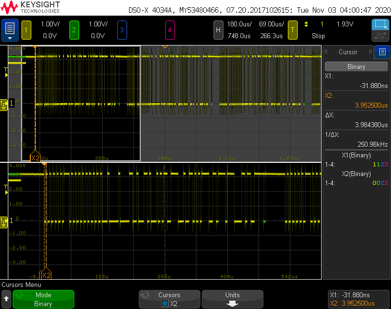
Am I misunderstanding what rxMsgData is? Should I be able to see the data either update with the counter or when debugging is paused? If not is there a way I can do this? Here are some screenshots:

Screen Shot 2020-11-02 at 11.54.15 AM.png

Thanks,

Youssef

  • Youssef,

                  The correct document to refer for this device is http://www.ti.com/lit/sprace5. Recently released http://www.ti.com/lit/spracq3 depicts lot of easy to understand waveforms. 

    Anyway, the fact that you see TxOK set in the transmitter and RxOK set in the receiver tells me that the frames are going out correctly and this is unlikely to be a H/W issue. 

    I am unable to see your screenshots. Could you attach them again please? Use the attach option shown below:


  • Hi Hareesh,


    Thank you for the response and the documentation I will read through them. I agree that it seems to be a software issue so in the meantime here are the screenshots. (edited to add another where info was cut off)

  • I will await your response. In the interim, I have 3 questions:

    1. Can you capture the bus activity with a scope? This way, we can confirm exactly what is coming out of the CANTX pin.
    2. What version of CCS are you using?
    3. Can you try reading directly from the RAM locations? (as opposed to the Expressions window)

  • In order to look with the scope I've had to attach both C2000s to one computer but I've created a custom target config and have the same error. Attached is a screenshot of the D and R pins of the transceiver (yellow is D) of the board that has the simple transmit code on it.  

    Unfortunately, my scope does not have CAN triggering so it's just a overview and zoomed in shot. A couple things I noticed is that the smallest "bit" is at frequency of 250k rather than the set 500kbps and that the D pin is at ~2.7V before the code is loaded before being pulled up to 3.3V, not sure if that one matters. I am using CCS 9.3.0.00012 because I had other problems with the latest release. 

  • I just saw your edited response but I do not know what you mean exactly, should I be looking in the Registers tab or the memory tab? Please let me know exactly what you need and how I can show it.


    Thanks again,

    Youssef

  • The scope capture shows some activity, but I am unable to discern anything meaningful from it. 

    As to why bit-rate is 250 kbps,please take a look at the last post in this thread: https://e2e.ti.com/support/microcontrollers/c2000/f/171/t/948586. In any case, this cannot be the issue, since both transmitter and receiver are affected the same way (and are operating at 250 kbps) 

    should I be looking in the Registers tab or the memory tab?

    It appears the receive buffer starts at AB24 in dataspace. Open that address in the Memory Browser and check what values are contained there. You can also directly examine the mailbox RAM.

  • The values appear to be zero in that view as well:

    Also I retried loopback mode for both boards and it still works properly, I only have this error when I use two separate boards, rx and txMsgData are one cycle behind which I believe is expected behavior:

  • RxOK is set, so something is being received. Unfortunately, you indicated your scope cannot decode. Do you have access to a USB-bus based CAN bus analyzer? You could get one for <$150. Without visibility to what is happening on the bus, debug is going to be painful.

  • Thank you to Hareesh for figuring this out. The default for ex4 (transmit) is the extended CAN frame while for ex5 (receive) it is the standard CAN frame. I just missed checking this. They obviously must match and the receive mailbox can simply be updated to CAN_MSG_FRAME_EXT.

    Before:

    CAN_setupMessageObject(CANB_BASE, 2, 0x200,CAN_MSG_FRAME_STD, CAN_MSG_OBJ_TYPE_RX, 0,CAN_MSG_OBJ_NO_FLAGS, MSG_DATA_LENGTH); 

    After:  

    CAN_setupMessageObject(CANB_BASE, 2, 0x200,CAN_MSG_FRAME_EXT, CAN_MSG_OBJ_TYPE_RX, 0,CAN_MSG_OBJ_NO_FLAGS, MSG_DATA_LENGTH); 

    Thanks again to Hareesh!