This thread has been locked.

If you have a related question, please click the "Ask a related question" button in the top right corner. The newly created question will be automatically linked to this question.

CCS/BOOSTXL-BUCKCONV: Designing a Variable power supply with C2000

Part Number: BOOSTXL-BUCKCONV
Other Parts Discussed in Thread: POWERSUITE, TIDM-DC-DC-BUCK, LAUNCHXL-F280049C, SFRA, C2000WARE, INA293, INA198

Tool/software: Code Composer Studio

Hi Experts,

I want to design a custom power supply with below specifications. I want to use BOOSTXL-BUCKCONV As a reference design and Want to use F28379D as a Controller (I need 4mV/1mA measurement accuracy so need 16-bit resolution).

Vin: 72V

Vo: 0.8V to 65V

Iout: 0 to 6.5A

Now, I see that the power suit calculates the coefficients based on my I/O requirements. Now I want this power supply to run independently and It should be programmable to any voltage between 0.8 and 65 Is it possible to design this supply with the help of this reference design? Where Can I find the theory behind the digital power design and Some tutorials about it?

Recently I posted a few queries regarding this. Though of going with Buck converter IC with DAC for controlling the output voltage. But that's not suitable for the range I am looking at. I found that digital control is well suited for applications like this. But unfortunately, it's a new technology and has very less info about it.

Regards

Vishal

  • Vishal Kakade1 said:
    Now I want this power supply to run independently and It should be programmable to any voltage between 0.8 and 65 Is it possible to design this supply with the help of this reference design?

    The design will certainly help with providing a software framework and reference for how to configure the device for a basic buck topology.

    Vishal Kakade1 said:
    Where Can I find the theory behind the digital power design and Some tutorials about it?

    We have some materials that describe how digital power control can be implemented on a C2000 device (General, PCMC, Workshop) and a number of examples for specific topologies in the Digital Power SDK.  However, these all assume that the user has a working understanding of power conversion and control theory.  There is a lot of material available in the public domain that can cover the basics (training, white papers, YouTube, TI Training Portal, etc).

  • Hi,

    The workshop Is Discontinued. And the video content is removed. How can I get it? 

    I want the power supply to be controlled from outside(without using the tool every time to change the voltage). Can this be done in the code itself? or every time the tool has to generate the coefficients for different voltage?

    Regards

    Vishal

  • Vishal,

    The workshop was developed with only printed materials, which you can download from the training page.  The hardware has been discontinued, but the core topology used was very similar to the BOOSTXL-BUCKCONV BoosterPack.

    A C2000-based power supply can certainly operate in the standalone fashion that you describe with some development effort.  Please keep in mind that the examples provided are typically meant to be used for demonstration purposes, as opposed to turnkey designs that can be productized without modification.  The PowerSUITE GUI options help to demonstrate how a modular program can be adapted to different use cases with minor changes.

    I would recommend following the TIDM-DC-DC-BUCK walkthrough using the BOOSTXL_BUCKCONV + LAUNCHXL-F280049C hardware to get a feel for how the system operates.  If it meets your needs, you can then modify the non-powerSUITE project (buck_nonpowerSUITE) to run standalone on F2837x.

    -Tommy

  • Hi Tommy,

    Today, I tried the Buck Converter design with BOOSTXL-BUCKCONV + TMS320F28004C launchpad. I am quite happy with the results. Now I will port this design to my requirement of 65V output. I need help with the Below points.

    1.  If I design a custom board, The SFRA, Compensator will they work with the JTAG or I need a UART interface as well like the launchpad.
    2. Where Can I learn more about the theory part like the compensation for digital power, what is the mathematics involved, What are the coefficients are shown in SFRA, How they affect the design, more understanding of the Firmware code, etc.
    3. With F28004 and a Voltage range of 65V, the measurement resolution will be around 15mV. I am looking for a resolution of <4mV. So Planning to move to F28379D (16bit ADC and have coding experience with F28379D). How to create the GUI for generating the user parameters file as shown for F28004 example, How to port the code for F28004?
    4. I need an adjustable voltage range for the entire 65V. How does this affect Calculating the Open-loop gain and generating the SFRA/Compensation coefficients? If yes, Can the program automatically achieve it for the entire voltage range without using SFRA for every voltage?
    5. Also, I would Like to simulate this in TINA12 (The industrial version) I need the Simulation model of the MCU. (Tina12 has only TM4C123XXX MCU's. How to get the simulation model of other MCU's)?

    I want to understand the complete working of theory and Mathematics involved.

    Regards

    Vishal

  • Hi Vishal, Tommy is out of the office this week due to US holiday, you can expect a reply back by Tuesday or Wednesday next week.  I apologize for the delay.

    Regards,

    Joe

  • Vishal Kakade1 said:
    If I design a custom board, The SFRA, Compensator will they work with the JTAG or I need a UART interface as well like the launchpad.

    The SFRA library is currently implemented to only work through a UART interface.  The buck converter example uses the UART port embedded in the XDS110, and the PC GUI communicates through a COM port.

    Vishal Kakade1 said:
    Where Can I learn more about the theory part like the compensation for digital power, what is the mathematics involved, What are the coefficients are shown in SFRA, How they affect the design, more understanding of the Firmware code, etc.

    There is a lot of information in the public domain.  Unfortunately, most of the TI documentation that I have seen assumes that the user already has a working understanding of the concepts.

    I have come across introductory white papers and online videos that are available for free.  I know there are some fee-based online Power Electronics courses at places like Coursera.  There is in-person training available from providers like Biricha.  And I suppose there are always traditional textbooks and university courses.

    Vishal Kakade1 said:
    With F28004 and a Voltage range of 65V, the measurement resolution will be around 15mV. I am looking for a resolution of <4mV. So Planning to move to F28379D (16bit ADC and have coding experience with F28379D). How to create the GUI for generating the user parameters file as shown for F28004 example, How to port the code for F28004?

    I would recommend using the nonpowerSUITE project.  All of the SysConfig-customizable options in the GUI can be updated directly in the buck_settings.h file. There is also the TIDM-DC-DC-BUCK_Calculations.xlsx file in the hardware directory to show how to recalculate the PU ranges.

    Vishal Kakade1 said:
    I need an adjustable voltage range for the entire 65V. How does this affect Calculating the Open-loop gain and generating the SFRA/Compensation coefficients? If yes, Can the program automatically achieve it for the entire voltage range without using SFRA for every voltage?

    The control coefficients can definitely be updated at run-time.

    I don't think that I have enough experience to provide proper guidance with respect to whether you would need to characterize using SFRA at each set point.  My guess would be that the first-order behavior would be fairly consistent while in CCM, but there will be lesser second-order variation along the range.

    Vishal Kakade1 said:
    Also, I would Like to simulate this in TINA12 (The industrial version) I need the Simulation model of the MCU. (Tina12 has only TM4C123XXX MCU's. How to get the simulation model of other MCU's)?

    Luckily, this ADC Input appnote was just published.  Maybe the models can be imported.

  • Hi,

    Thanks for your response.

    1. If I design a board with a UART port (Same as the example uses with FTDI chip) and JTAG, Can the SFRA work?
    2. The link you provided, Only has ADC modeling. I need the complete MCU macro model for the simulation.
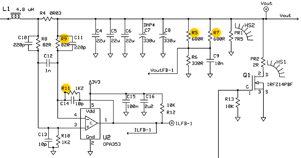
    3. Where Can I find the nonpowerSUITE projects? also, TIDM-DC-DC-BUCK, There are few components like R5//R7. But its nowhere in the image shown

    Regards

    Vishal

  • Vishal Kakade1 said:
    If I design a board with a UART port (Same as the example uses with FTDI chip) and JTAG, Can the SFRA work?

    Yes, this will work.

    Vishal Kakade1 said:
    The link you provided, Only has ADC modeling. I need the complete MCU macro model for the simulation.

    I am not aware of a TI-generated MCU macro model.  There are BSDL and IBIS models, but nothing like what you are describing.

    Vishal Kakade1 said:
    Where Can I find the nonpowerSUITE projects?

    This is a CCS project that would be imported from ~\C2000Ware_DigitalPower_SDK_XXXX\solutions\tidm_dc_dc_buck\f28004x\ccs\buck_nonpowerSUITE.projectspec

    Vishal Kakade1 said:
    also, TIDM-DC-DC-BUCK, There are few components like R5//R7. But its nowhere in the image shown

    These can be found in the schematic:

  • Hi,

    • Where Can I find an explanation for the software?
    • The buck_nonpowerSUITE project is for F28004X. What all the changes needed to port it to F28379D?
    • Instead of U2-OPA353 for current sensing, Can I directly use some current sense amplifiers? like INA293/INA198 etc?
    • Tina has a complete simulation (circuit) model for more than 1000 MCU's including TM4C123, Arduino, etc. Similarly, I need the simulation model of C2000 MCU's.
    • I am having trouble with CCS. The resource explorer is not opening sometimes.

    Regards

    Vishal

  • Vishal Kakade1 said:
    Where Can I find an explanation for the software?

    The primary documentation is in the form of the TIDM-DC-DC-BUCK walkthrough guide. Beyond that, the expectation is that users will be able to follow the code execution to understand the flow. Specific questions can be posed to this forum.

    Vishal Kakade1 said:
    The buck_nonpowerSUITE project is for F28004X. What all the changes needed to port it to F28379D?

    The example was written using driverlib functions. As such, the majority of the function calls will be identical to other C2000 devices with driverlib support.

    The primary changes would be to update the dependencies to use F2837x driverlib instead of F28004x driverlib, and then adapt the device resources and drivers that are defined in buck_user_settings.h and buck_hal.[ch].

    The walkthrough document has an Adapting This Solution section that describes how the example is modularized.

    Vishal Kakade1 said:
    Instead of U2-OPA353 for current sensing, Can I directly use some current sense amplifiers? like INA293/INA198 etc?

    Sure, the software can be customized to accommodate such differences.

    Vishal Kakade1 said:
    Tina has a complete simulation (circuit) model for more than 1000 MCU's including TM4C123, Arduino, etc. Similarly, I need the simulation model of C2000 MCU's.

    As far as I know, TI has no plans to create full MCU Tina models for C2000 devices. I suspect that the models might be generated by Tina. If so, it would be up to them to support C2000.

    Vishal Kakade1 said:
    I am having trouble with CCS. The resource explorer is not opening sometimes.

    If you already know which example you want to use, you can access the projects in the file system directly using the CCS Project Import  function.