This thread has been locked.

If you have a related question, please click the "Ask a related question" button in the top right corner. The newly created question will be automatically linked to this question.

TMS320F28379D: Programming without CCS and source code

Part Number: TMS320F28379D
Other Parts Discussed in Thread: C2000WARE, TMDSCNCD28379D

Hi,

We're using the 28379D microcontroller in one of our product.

If we have to do an software update when the product is at the customer, how proceed ?
Is it possible to program the DSP without Code Composer and without the source code ?

Maybe with an other software ? Or with the source code in another format ?
Can we used the USB function of the microcontroller?

Thanks for your answer. 

Regards,

  • Hello, 

    The serial flash programmer and SCI flash kernel can help with this. You can find the serial flash programmer utility in C2000Ware at C2000Ware_x_xx_xx_xx\utilities\flash_programmers\serial_flash_programmer and the flash kernel project for F2837xD at C2000Ware_x_xx_xx_xx\device_support\f2837xd\examples\dual\F2837xD_sci_flash_kernels

    For information on how to use the SCI flash kernel and serial flash programmer, please refer to ti.com/lit/sprabv4 

    Regards,

    Anu

  • Hi Anu,

    Thank you for your answer.

    I've read the sprabv4 application note, but it's not possible for us to proceed like this. 
    If we have to ask the customer to load a new software version, it's too complicated.

    Are there another ways to proceed ? I don't know, using the USB to JTAG emulator, USB function of the microcontroller, ... ?

    Regards,

  • Maybe we are not understanding your requirements/use-case correctly. What Anu described above is typically how firmware updates are done in the field after deployment. They don't use CCS or JTAG. A host sends a firmware update command along the new firmware image to be downloaded. The app note above illustrates it using SCI, but it could just as well be USB or CAN or other.

    Let us know.

  • Hi,

    I'm sorry if I'm not clear.

    If I want to do a firmware update, I just want to :

    • send the new firmware update to the customer (by mail for example)
    • he copy this image on an USB key for example
    • he plug the USB key on the microcontroller
    • After pressing a button (for example), the update is done

    I just don't want customer to plug a laptop on the MCU and use a software to update the firmware.

    I don't know if I'm more clear and if it's possible?

    Thank you,

  • When you say "he plugs the USB key on the microcontroller", I don't know that it's as simple as that in a production environment.

    Depending on the application the Microcontroller is targeted towards e.g. Digital Power or Motor Control, the Microcontroller board may not even be physically accessible to you. So typically what customers will do is develop a firmware update mechanism in advance, using one of the peripherals available (e.g. SCI, USB, CAN), a communication channel that comes out to an external host (such as a PC) or I think it can even be another host microcontroller that is in charge of issuing the firmware update command. Eventually it comes down to this, if you had to break it down into very simple steps:

    1. You prepare a new firmware image

    2. You share it with customer (mail/email/online etc.)

    3. The customer has the new image on their computer. They run a firmware update command directly from their computer to the Microcontroller, or there's some way of handing off this image to the Host microcontroller which will run the firmware update command, and update the Microcontroller firmware.

    So I think you need to think through the specifics of this in your particular case.

    Thanks,

    Sira

  • Hi Sira,

    Thanks for your answer.

    If I create a firmware image and I copy it on an USB key, I just want to know if it's possible to read it with the USB function of the MCU, and then program the Flash memory.

    I currently do it with an SD card and spi bus, and it works.

    I hope I'm clear.

    Regards,

  • Yes, in general, you can use the USB peripheral also to update Microcontroller firmware. You will need a USB Flash Kernel (Bootloader) for the Microcontroller. We have examples for these kernels for SCI/CAN/USB for various devices. We have it for the following devices:

    • SCI (F2802x, 03x, 05x, 07x, 37xS, 37xD, 004x)
    • CAN (03x, 06x) - \device_support\f2806x\examples\c28\f28069_can_flash_kernel,  \device_support\f2803x\examples\c28\f2803x_can_flash_kernel
    • USB (37xD)
  • Thanks.

    Can you tell me where are the examples and documentations please ? I find nothing in C2000.
    I use a F28379D MCU.

    Regards,

  • C:\ti\c2000\C2000Ware_3_03_00_00\device_support\f2837xd\examples\dual\F2837xD_usb_flash_kernels

  • Hi Sira,

    Just one last question ; if I use USB Flash Kernel, does my Boot Mode Pin state (GPIO72 & 84) have to change during or after reprogramming ?
    Because currently, pins state is GPIO72 = GPIO84 = 1 (Get Mode (Flash by default))

    Thank you.

    Regards,

  • For me we don't have to ; as I explained, currently I'm using SPI bus to read a SD card, I write these values in the Flash and I restart the MCU. And the boot mode is the same (Flash by default)

    I want to do the same thing with the USB ; just reading values that are on the USB key, writing it on the Flash and restart the MCU.

    So for me I don't need to change the boot mode.

    Regards,

  • There are a few ways of doing this. One way is to boot in USB boot mode, the USB ROM bootloader will run and download the USB Flash Kernel to RAM, transfer control to it. Then the USB Flash Kernel in RAM will download your application to Flash.

    Another option is to have the USB Flash kernel in dedicated sectors in Flash, and then you can always boot in Flash boot. Have the Boot to Flash entry point enter a desired function in the USB Flash Kernel, which will either boot the Application or allow Firmware upgrade via USB.

    Thanks,

    Sira

  • Hi Sira,

    Sira Rao80 said:

    Another option is to have the USB Flash kernel in dedicated sectors in Flash, and then you can always boot in Flash boot. Have the Boot to Flash entry point enter a desired function in the USB Flash Kernel, which will either boot the Application or allow Firmware upgrade via USB.

    Yes, it can be an option, but it means that every time the microcontroller will boot, the entry point will be the function in the USB Flash Kernel, are you agree ?

    I need this case only when the customer want to update his firmware, no every time we have a reboot.

    How can I proceed ?

    Thank you very much for your support.

    Regards,

  • Yes, you are right, which is why the first approach is maybe what you want to use, which I paste again below:

    "boot in USB boot mode, the USB ROM bootloader will run and download the USB Flash Kernel to RAM, transfer control to it. Then the USB Flash Kernel in RAM will download your application to Flash."

    So when you want to upgrade firmware, you boot in USB boot mode (change the GPIO boot mode pins to USB boot), when you want to run the application from Flash (normal operation, keep the GPIO boot mode pins at Flash boot).

    Thanks,

    Sira

  • Hi,

    Good news if it's possible.

    Is it possible to change boot mode by soft ? Or is it possible only by hardware ?

    Regards,

  • It is possible, please refer to spracn1. Also refer to sprabv4 (which I think I already pointed you to).

    Thanks,

    Sira

  • Ok, thank you very much.

    This is the last question of this post :

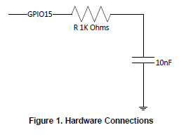
    In the case of the TMS320F28004x microcontroller , we can use this hardware.

    • By default, boot mode is GPIO15 = 0 (Flash mode)
    • When I want to use SCI boot mode, we have to charge the capacitor at least 50µS (GPIO15 = 1), reset the MCU, and the pin turns back into an input, it can drive high long enough for the boot code to read it as high.

    Understood.

    But in my case, I need the opposite :

    • By default, boot mode is GPIO72 = 1 (Flash mode). I'll use a pull-up resistor.
    • When I want to use SCI boot mode, I need GPIO72 = 0. If I set GPIO72 = 0 in the software before reset, will the MCU boot in the SCI boot mode ?

  • Let me check and get back to you.

  • Ok, waiting for your answer.

    Thank you,

  • As I think more about this, I'm not sure that will work. As soon as you reset the device, the pull up will lift the GPIO high again. So it will again boot in Flash mode itself. There has to be some capacitive effect for this to work.

    Why don't you use the exact method suggested here? GPIO72, 84 are the defaults, but you can always customize it as this app note shows.

    Thanks,

    Sira

  • Hi Sira,

    So if I want by default a Flash boot for normal operation, I need high level on GPIO72 & GPIO84 (with pull-up).

    If I want a USB (SCI) boot mode to upgrade the firmware, I can proceed without changing the hardware ?

    That's what I understood in the app notes :

    There are a few options here. A few are mentioned in Section 6.3 - the device can boot up in Flash boot mode for normal operation, and in SCI Boot mode for firmware upgrades. The user will need to design a scheme that allows changing the boot mode select pins settings. Alternately, the user can decide to only use the Flash boot mode, and then in software, branch to the SCI Boot function. This can be through an IO trigger or host command, that serves as a cue to call the SCI_Boot() function. The advantage of this approach is that the user does not need to change the boot mode select pins settings. Note that in this case, the SCI ROM Bootloader is not invoked.

    Can you confirm ?

    Thank you

  • This is really implementation specific. I think customers do this differently. For example, once you boot in Flash boot, the entry point can be into a function in the custom bootloader (Flash kernel). Here, it can test a GPIO pin to check if a Firmware update needs to be done. Alternately, it can wait for a short time period to see if the host sends a Firmware update command. If either of these occurs, it can run the firmware update. Otherwise, it can branch to the entry point of the application, typically where a branch to the C initialization routine (_c_int00) occurs and from where main() of the application is called.

    Thanks,

    Sira

  • Ok, thank you.

    So in my case, if I want to use an USB peripheral (usb key for example) to do a firmware update, my MCU must be in host mode or it can be in device mode ? (I will read a file on the USB key to do the update).

    I'm using the PTP package of the F2839D, and pins USB0PFLT and USB0EPEN are not available.

    Can it works in device mode ?

    Thank you.

    Regards

  • I'm not sure I understand the question. I am not aware of host/device modes? Can you elaborate?

    My understanding of your scenario is that a host will send the firmware via USB to the F28379D device.

    Thanks,

    Sira

  • Sorry if I wasn't clear.

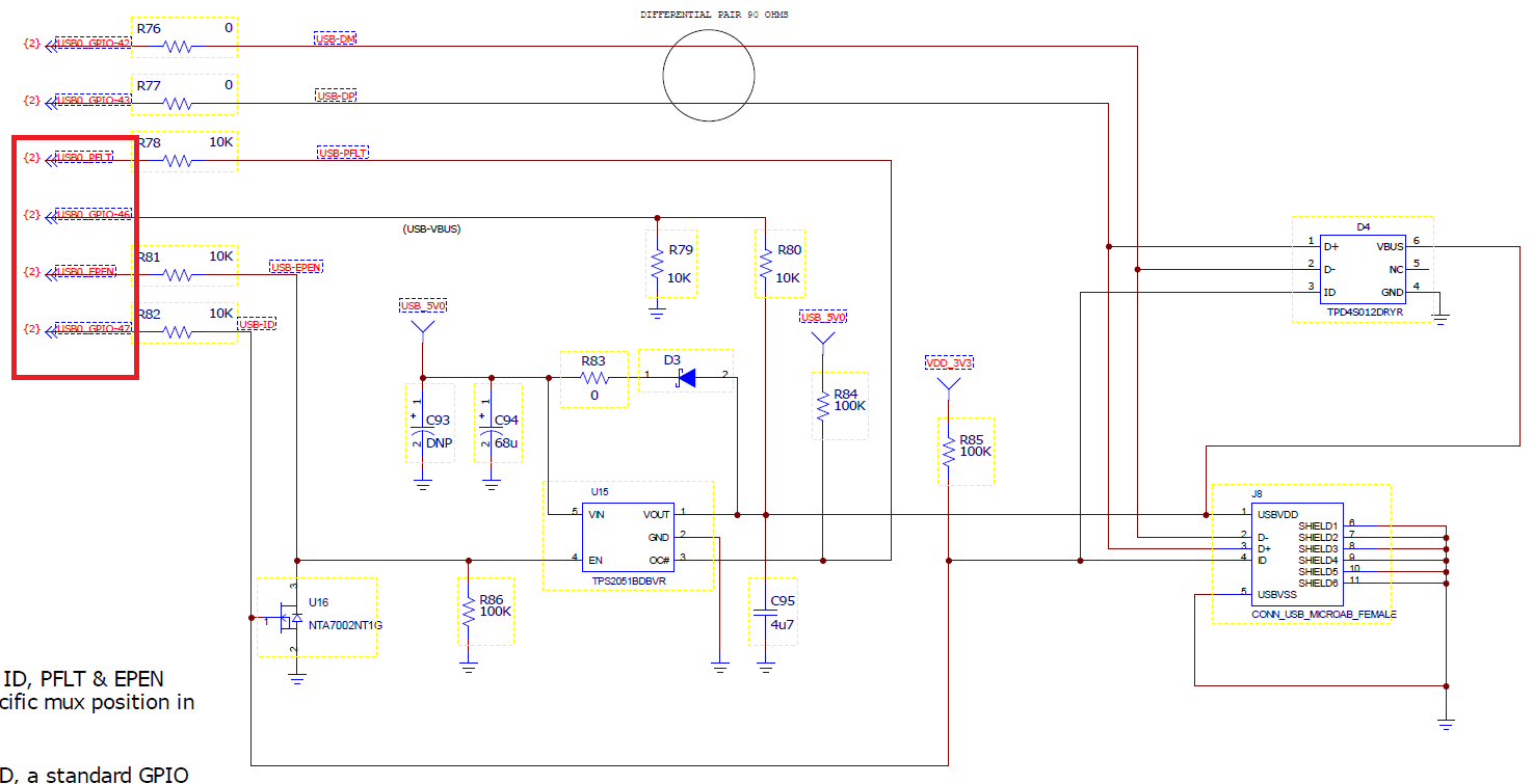
    Yes, based on the schematic of the TMDSCNCD28379D control card, I want to do a firmware update : 

    An USB key with the firmware image will be plug on the USB connector (on the schematic J8). The MCU must read this image and do the firmware update.

    Is it clear for you ?

    So I have 2 questions : 

    • I'm using the PTP package (176 pins) and pins in red (USB0-EPEN and USB0_PLFT) are not available. Is is mandatory ?
    • Do I have to use the entire scheme?

    Thank you for your support.

    Regards,

  • I am going to re-assign this issue to a USB expert to help you.

    Thanks,

    Sira

  • Hi,

    Ok, waiting for your answer.

    Regards,

  • Hi,

    The USB bootloader cannot be used with a USB key/pen drive.  USB bootloader acts as a device, and to operate with a mass storage class it would need to operate as a host.

    If you still want to use MSC for updating the firmware, you can take a look at the usb_ex7_host_msc example, and read from the USB Mass Storage and then update the firmware with what is read.

    Hope this helps.

    Best Regards

    Siddharth

  • Hi Siddharth,

    If I want to use update the firmware with an USB key, I have to operate as a host ?

    So with the PTP package (176 pins), it's not possible ? ((USB0-EPEN and USB0_PLFT are not available)

  • Hi,

    Yes, in host mode, the USB controller is responsible for supplying power to the bus. 

    EPEN signal is used to enable or disable power to the VBUS pin on the USB connector.

    PFLT, provides feedback when there has been a power fault on VBUS. 

    Best Regards

    Siddharth

  • Hi,

    So the only solution for me is to change the MCU package to have these signals ?

    Regards

  • yes, on the PTP package , these signals are not available.

    Best Regards

    Siddharth