This thread has been locked.

If you have a related question, please click the "Ask a related question" button in the top right corner. The newly created question will be automatically linked to this question.

TMS320F28069M: Reading frequency with eQEP

Part Number: TMS320F28069M


Hi,

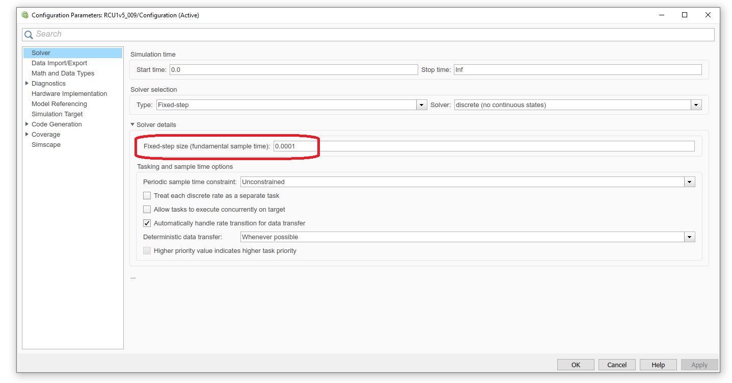
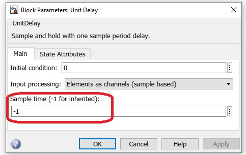
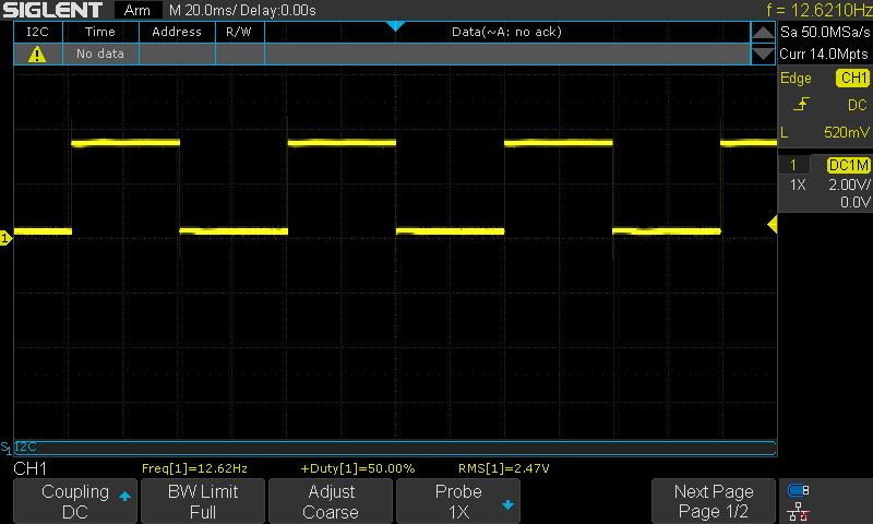
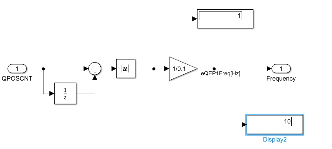
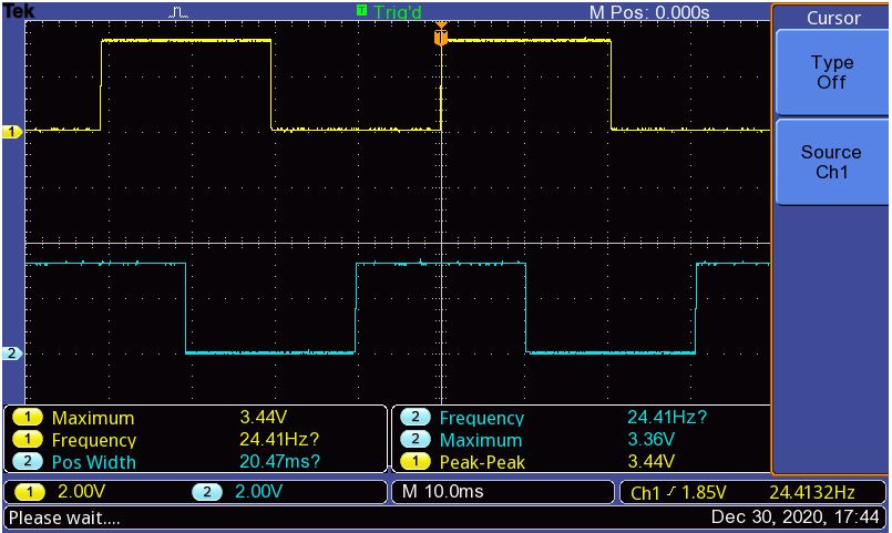
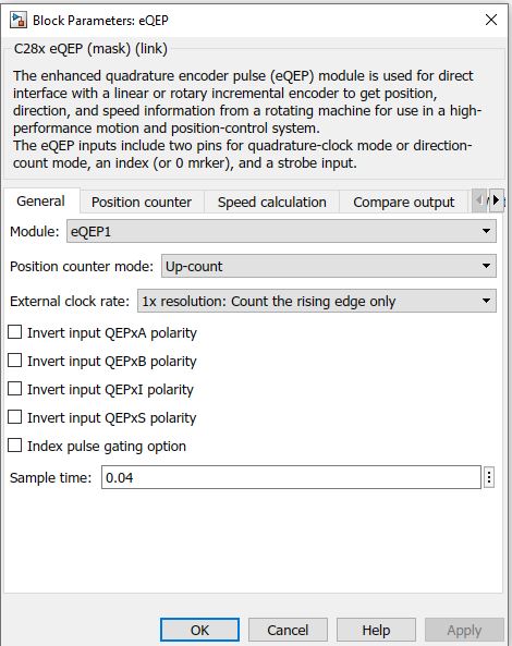
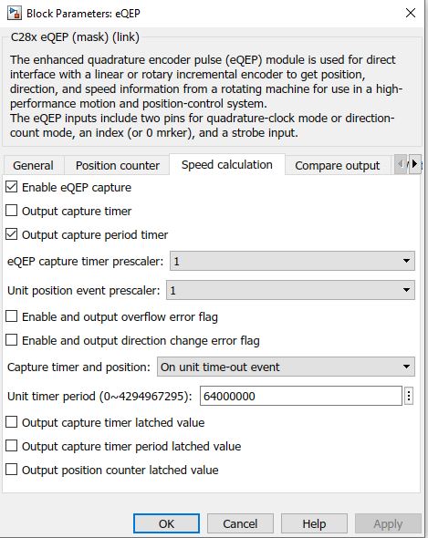
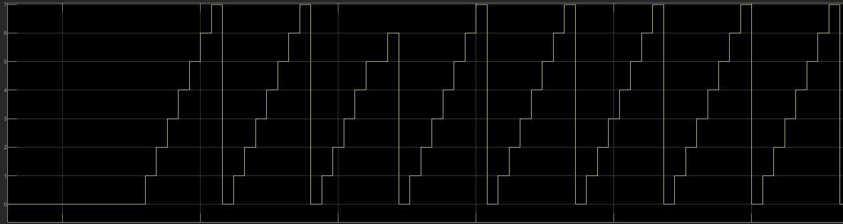
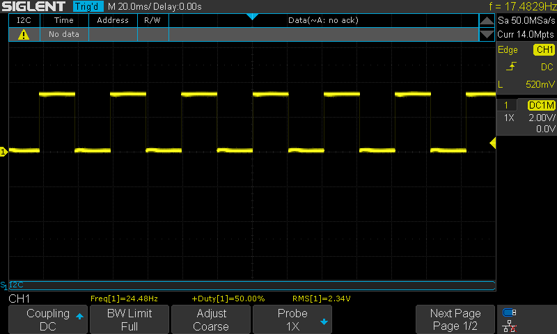
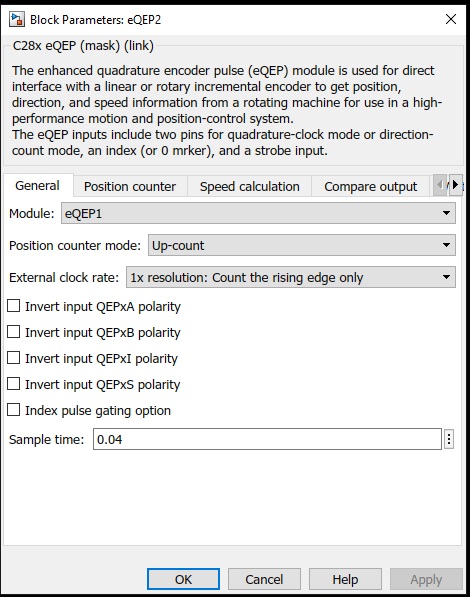
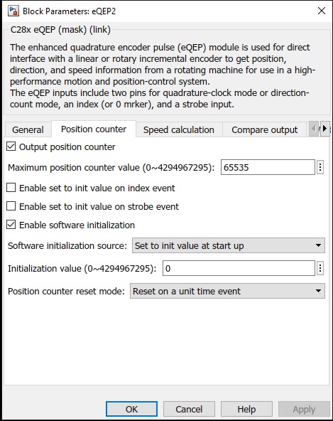
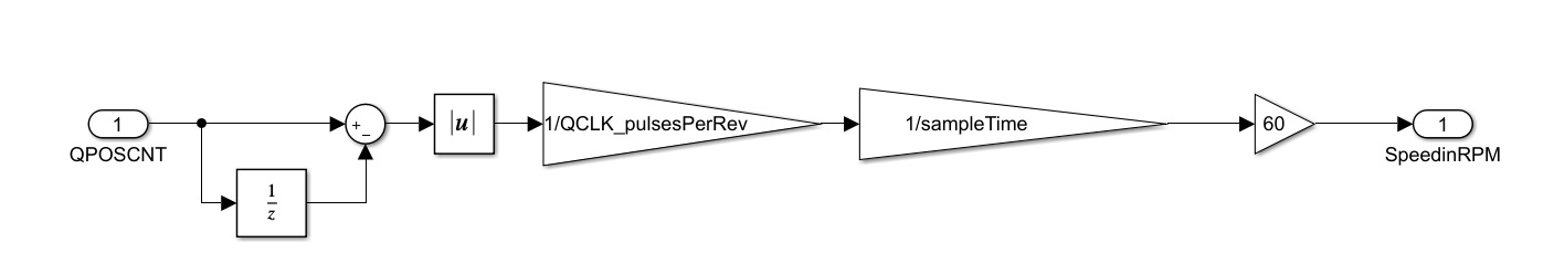
I'm using Matlab/Simulink to read frequency input using eQEP channel but I'm not quite successful. I read the user manual and I understand that the "position counter mode" should set to "Up-count" and the "position counter reset mode" should set to "reset on a unit time event". I'm still confused on how other setting should look like. I found an example online that uses the below logic, but I'm not sure how the calculation is derived: 

The eQEP document does not clearly describe how to setup the module to read frequency. Any advise would be appreciated.

  • Hi Kash,

    Measuring frequency using the eQEP module and Up-count mode involves counting the number of pulses (QPOSCNT) on the input signal and dividing the counts by the amount of time (unit time event). The example you have looks to calculate RPM, which you can convert to frequency by dividing by 60.

    I'm not familiar with configuring and using the eQEP using Matlab/Simulink. I'll have another expert comment on any specifics using those tools.

    Best,

    Kevin

  • Hi Kevin,

    Thanks for the reply. 

    I'm able to read the frequency by dividing QPOSCNT by the unit time event. I guess I'm doing something wrong in my calculation, my unit time is 0.0001 second but I have to divide QPOSCNT by 0.1 to get the correct frequency in Hz. 

  • Hi Kash,

    Kevin is out of office this week due to US holidays. He will return & get back to you by Dec 1st. 

    Hopefully you can continue to make progress in the mean-time.  Good luck!


    Thank you,
    Brett

  • Thanks Brett for the message. I will keep working on it.

  • Thank you for your understanding, Kash. 

    -Lori

  • Hi Kash,

    Sorry for the delay.

    Kash Olia said:
    0.0001 second but I have to divide QPOSCNT by 0.1 to get the correct frequency in Hz. 

    What is your test setup? If you're only dividing QPOSCNT value by the expected time for your calculation there must be some configuration that's mixed up. Verify that your unit time event is configured to occur at the correct time. Also that your in up count mode (QSRC) and only counting rising edges (XCR).

    Feel free to post screenshots of your conifg if you have more details to share.

    Best,

    Kevin

  • Hi Kevin,

    Here is the screenshot of time config for the entire Simulink model:

    Here is the Unit Delay time config: 

    And here is the eQEP block:

    Thanks,

  • I also have an issue with low frequency, position counter reading works fine for frequency above 200Hz but for lower values it's not accurate, it cannot measure any frequency less than 20-30 Hz. 

    Any help would be appreciated.  

  • Hi Kash,

    Myself or another expert will get back to you tomorrow on this topic. Sorry, but I did not get a chance to look into it much today.

    Thanks,

    Kevin

  • No worries, I appreciate the help.

  • Hi Kash,

    I'm not familiar with the Simulink tool specifics you've shown in your screenshots. Someone from the Mathworks team that is more familiar has been notified of your post and should reply on here relatively soon.

    I appreciate your patience.

    Best,

    Kevin

  • Hi Kash,

    I am trying to setup a simple model to verify this.

    Do you see any output from the block for frequency range of 20-30Hz?

    Please let me know if you can attach the model here.

  • Hi Venkatesh,

    Yes, I see some random numbers when the frequency gets to 20Hz, but it's not consistent. 

    Please find the model attached. https://e2e.ti.com/cfs-file/__key/communityserver-discussions-components-files/171/eQEPTestMdl.7z

  • Kash,

    We have sent email reminder to MathWorks team to review the attached model.

  • Thanks Santosh.

  • Hi,

    We use QEP module in one of the latest shipping examples.

    I learnt that the sensor offset correction algorithm runs the motor at low speed i.e around 1 RPM. And they are able to get meaningful counts and calculate the offset. So it is unlikely the block has an issue. Please can you verify if your input to eQEP module is consistent? You can also study this example and QEP block configuration if that helps.

  • Hi Venkatesh,

    Yes, the input is consistent. I have oscilloscope connected to the input and I can see the waveform with a fixed frequency. 

    Thanks for the link, I will look into it and try to run the example, it might help troubleshoot the issue.

  • I ran the test again using the board's PWM channel to make sure I'm getting consistent frequency input. Below is the PWM waveform generated by the GPIO0 (ePWM1-A):

    But the result of QPOSCNT after post processing is jumping between 10 and 20:

    If I want to read 12.6Hz as the input frequency, the output of absolute block should be 1.26 but the QPOSCNT data type is always integer, so it makes sense why I don't see the right frequency. 

    I changed the position counter datatype to single and double but did not see any value output other than integer. Am I supposed to see non-integer value?

    P.S: I was not able to run the example that you mentioned above as I'm using 2018b version of MATLAB. 

    Thanks,

  • Kash,

    Sending the email reminder to MathWork team. Due to holiday, many folks are out of office, so response may be delayed. 

  • Thanks Santosh and Happy Holidays!

  • Hi Kash,

    I quickly setup 2 ePWM modules to generates the quadrature output and used the same as input eQEP module.

    The input frequency is 24Hz. Please find the attached snap.

    Since I had access only to F28379D launchpad board, I used the same for this experiment. However, the results would be same on any other controller that we support. I then tried to configure the eQEP block as below:

    Since the input frequency is 24Hz, it made sense to read the count at 1/24 = 0.04 step time.

    Next the configuration for Position counter:

    Finally under the Speed calculation I set the 'Unit timer period' to 64000000.

    i.e with 200MHz sys clock which is true for F28379D, it would take 0.3200 for Unit timer period to rollover.

    And with 0.04 time for one count(24Hz) we would then get a count of 0.3200/0.04 = 8 (0 to 7).

    And this is exactly what I got when running the external mode.

  • Hi Venkatesh,

    Thanks for the detailed explanation. 

    I tried to replicate your test with F28069 at 90MHz clock. I generated a PWM signal with 24Hz and 50% DC as below. Although you generated two PWM signal but I noticed that you used the eQEP block in Up-count mode rather than Quadrature mode, so I only generated one PWM signal and connected to EQEP1A pin:

    Here are the snapshots from eQEP block. 

    I used the same the same sample time (just for the information the solver is set to fixedStepDiscrete at 0.0001):

    for the Position counter, I used the same setup as yours:

    For the speed calculation, I used 28,800,000 for "Unit timer period" to get the same count as yours (8) as my clock frequency is 90MHz: 

    8(count) * 0.04 (sample time) = 0.32

    0.32 * 90MHz = 28,800,000

    and here is the model and final result:

    The Position Counter (qposcnt) was jumping from 0 to 7 (and sometimes 8) and the Period (qcprd) remained at zero.

    That's weird, are you connecting the PWM output directly to EQEP1A pin? Are you using any pull-up resistors? 

    Happy New Year!

    Thanks,

  • Hi Kash/Venkatesh,

    Original problem in my mind is a classic quantization issue - If no edges seen in a fixed sample time, speed perceived as 0. Can be solved by bumping the sample time.

    But, a better approach will be to capture the time between edges. With a 32 bit counter counting 90MHz clock, you can get accurate speed of this slow signal with good resolution & range.

    dt(s) = dClk/90E6
    Speed(Hz) = N/(2*dt)  //N=1 if dt on every edge

    Joe