This thread has been locked.

If you have a related question, please click the "Ask a related question" button in the top right corner. The newly created question will be automatically linked to this question.

LAUNCHXL-F280049C: Problem with number of Micro-edge in HRPWM Phase-Shift Control

Part Number: LAUNCHXL-F280049C
Other Parts Discussed in Thread: C2000WARE, TIDA-010054

Hi, my name is Iulian Popa.

I´m a student from Univerity of Zaragoza in Spain. Im using one of your development board 'LAUNCHXL-F280049C' and I have some questions and problems when I´m trying to control some PWM signals.

First of all, Im using:

-  CodeComposer version 9.3

-  C2000Ware version 3.1.0.00

Finally, after the support of Nima Eskandari in my post (e2e.ti.com/.../954853) I have achieved a phase shift control where I am able to update both the phase shift and the high resolution phase shift. However, I have made a couple of tests to verify the correct operation of the MEP module(I have followed forum post to learn how to use this module).

I am using the internal oscillator of the MCU at a frequency of 10 MHz and using the PLL defines as follows:
#define DEVICE_OSCSRC_FREQ 10000000U
#define DEVICE_SETCLOCK_CFG (SYSCTL_OSCSRC_OSC2 | SYSCTL_IMULT(40) |
SYSCTL_FMULT_NONE | SYSCTL_SYSDIV(2) |
SYSCTL_PLL_ENABLE)
#define DEVICE_SYSCLK_FREQ ((DEVICE_OSCSRC_FREQ * 40 * 1) / 2)

With this I am able to generate 100 KHz PWM signals with a resolution of 5ns (TBPRD = 2000; Measured frequency = 100 KHz ; Resolution obtained 5ns).
Using the functions of the library "SFO_V8.h" each one of the coarse steps of 5ns divides them into 33 fine steps (150ps of resolution). However, in practice when I try to manually configure the EPwmxRegs.TBPHS.bit.TBPHSHR register with multiples of 256 from 256*1, 256*2, 256*3, 256*4 ...256*33 the phase shift obtained is not 150ps * 33 micro-steps = 5ns in fact the result is close to 2.5ns.


Why is it that the 33 steps indicated by the MEP module do not sweep all the coarse step?

A greeting. Iulian.

Translated with www.DeepL.com/Translator (free version)

  • Assuming you are using SFO, periodically in your code, have you enabled AUTOCONV in HRPWM setting?

    Nima

  • Hi Nima, 

    I´ve tried both, activated and desactivated. My HRPWM_Config function looks like this:

    void Config_HRPWM (void){
        SysCtl_disablePeripheral(SYSCTL_PERIPH_CLK_TBCLKSYNC); // Disable sync and clock to PWM
    
        uint16_t j;
    
        for (j=1;j<PWM_CH;j++){
            //-------------------------------------> High-Resolution ePWM <------------------------------------
            EALLOW;
    
                (*ePWM[j]).HRCNFG.all = 0x0;    //Clean all HRPWM bits
                (*ePWM[j]).HRCNFG.bit.EDGMODE = HR_BEP;  // MEP control on both edge
                (*ePWM[j]).HRCNFG.bit.CTLMODE = HR_PHS;  // TBPHSHR Control Mode
                (*ePWM[j]).HRCNFG.bit.HRLOAD  = HR_CTR_ZERO; //Load on CTR == 0
    
    //            (*ePWM[j]).HRMSTEP.bit.HRMSTEP = 33U;
    
                (*ePWM[j]).HRCNFG.bit.AUTOCONV = 0;     // Enable auto-conversion
    
                (*ePWM[j]).HRPCTL.bit.HRPE = 0; // Turn off high-resolution period control.
                (*ePWM[j]).HRPCTL.bit.TBPHSHRLOADE = 1; //TBPHSHR Load Enable
    
                (*ePWM[j]).HRPWR.bit.CALPWRON = 1; //Enables MEP Calibration LOGIC
    
            EDIS;
        }
        SysCtl_enablePeripheral(SYSCTL_PERIPH_CLK_TBCLKSYNC); // Enable sync and clock to PWM
    }

    I´ve tried to use and not SFO, use or not AUTOCONV but it´s always te same. 

    One of the last tests I did was to return the SYSCLK and PLL settings to the default values (10ns resolution / 100 MHz frequency). With this the SFO scales the fine steps to 66 (which is logical because 10ns / 66 micro-steps = 150ps that can be obtained with the MEP for the F280049C)
    However, when making the capture with the oscilloscope and manipulating manually the register TBPHS.bit.TBPHSHR I have realized that when I get to the value "TBPHS.bit.TBPHSHR = 55 steps * 256;" it is the last value that makes the PWM signal to move with respect to the master PWM, that is, if I change to "TBPHS.bit.TBPHSHR = 56 steps * 256;" there is no change and it is the same as if I put 66*256. Therefore, I am not able to sweep the 10ns with the 66 steps but I remain in 8.25ns which is a serious problem when implementing the control of my converter.

    Any clue about what could be the problem?

  • ENABLE AUTOCOV, then in that case, the HR portion of the EPWM register can go from 1-FF to cover the whole range.

    Nima

  • Also dont touch this register. It is used and handled by the SFO library.

    (*ePWM[j]).HRPWR.bit.CALPWRON = 1; //Enables MEP Calibration LOGIC

    Nima

  • Hello again Nima.
    I have removed the activation of the "CALPRWRON" bit from my configuration and have activated the HR auto-conversion. I've changed the configuration of the high resolution module and now I use the functions of the "driverlib" library (I've been seeing more answers from you in the IT forum to see if I found a solution to my problem while you were answering me).
    Now my high resolution module configuration looks like this:

    #include "SFO_V8.h"
    
    /////////////////////////////////////////////////////////////GLOBAL_DEFINITIONS////////////////////////////////////////////////////////////////////////////
    
    int MEP_ScaleFactor; // Global variable used by the SFO library
                         // Result can be used for all HRPWM channels
                         // This variable is also copied to HRMSTEP
                         // register by SFO() function.
    
    uint16_t status;
    
    // Used by SFO library (ePWM[0] is a dummy value that isn't used)
    volatile uint32_t ePWM[] = {0, EPWM1_BASE, EPWM2_BASE, EPWM3_BASE, EPWM4_BASE, EPWM5_BASE, EPWM6_BASE};
    
    ////////////////////////////////////////////////////////////INTO_MAIN////////////////////////////////////////////////////////////////////////////
    
        while(status == SFO_INCOMPLETE){
                status = SFO();
                if(status == SFO_ERROR){
                    error();   // SFO function returns 2 if an error occurs & # of MEP
                }              // steps/coarse step exceeds maximum of 255.
            }
    
        EALLOW;
    
        for(;;){
            if (status == SFO_ERROR){
                error();   // SFO function returns 2 if an error occurs & #// of MEP steps/coarse step exceeds maximum of 255.
            }
    
    ////////////////////////////////////////////////////////////AFTER_EPWM_CONFIGURATION///////////////////////////////////////////////////////////////////////////////
        uint16_t j;
    
        for (j=1;j<PWM_CH;j++){
            //-------------------------------------> High-Resolution ePWM <------------------------------------
    
            HRPWM_setMEPEdgeSelect(ePWM[j], HRPWM_CHANNEL_A, HRPWM_MEP_CTRL_RISING_AND_FALLING_EDGE); //MEP controls both rising and falling edge
            HRPWM_setMEPControlMode(ePWM[j], HRPWM_CHANNEL_A, HRPWM_MEP_PHASE_CTRL); //TBPHSHR controls MEP edge
            HRPWM_setCounterCompareShadowLoadEvent(ePWM[j], HRPWM_CHANNEL_A, HRPWM_LOAD_ON_CNTR_ZERO_PERIOD);         // MUST BE CTR=(ZER & PRD)
    
            HRPWM_enableAutoConversion(ePWM[j]); //Enables MEP (Micro Edge Positioner) automatic scale mode
    
            HRPWM_disablePeriodControl(ePWM[j]); //Disable high resolution period feature
            HRPWM_enablePhaseShiftLoad(ePWM[j]); //Enable high resolution phase load
        }

    I have used the initialization of the HR module that I have seen in one of your posts in the IT forum and I have adapted it so that it controls the phase shift and not the duty control.
    With this configuration I have tested what you have suggested in your answer and I have raised even more questions, I expose them below:

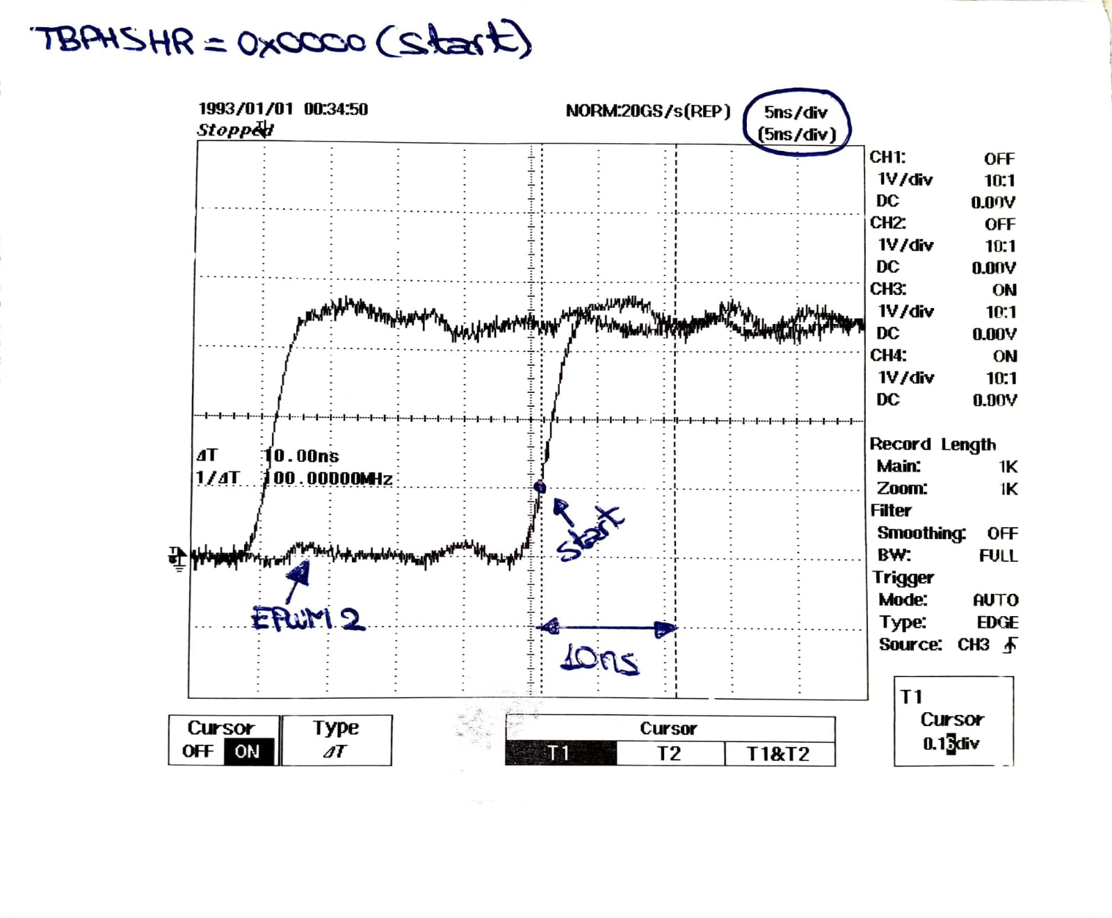
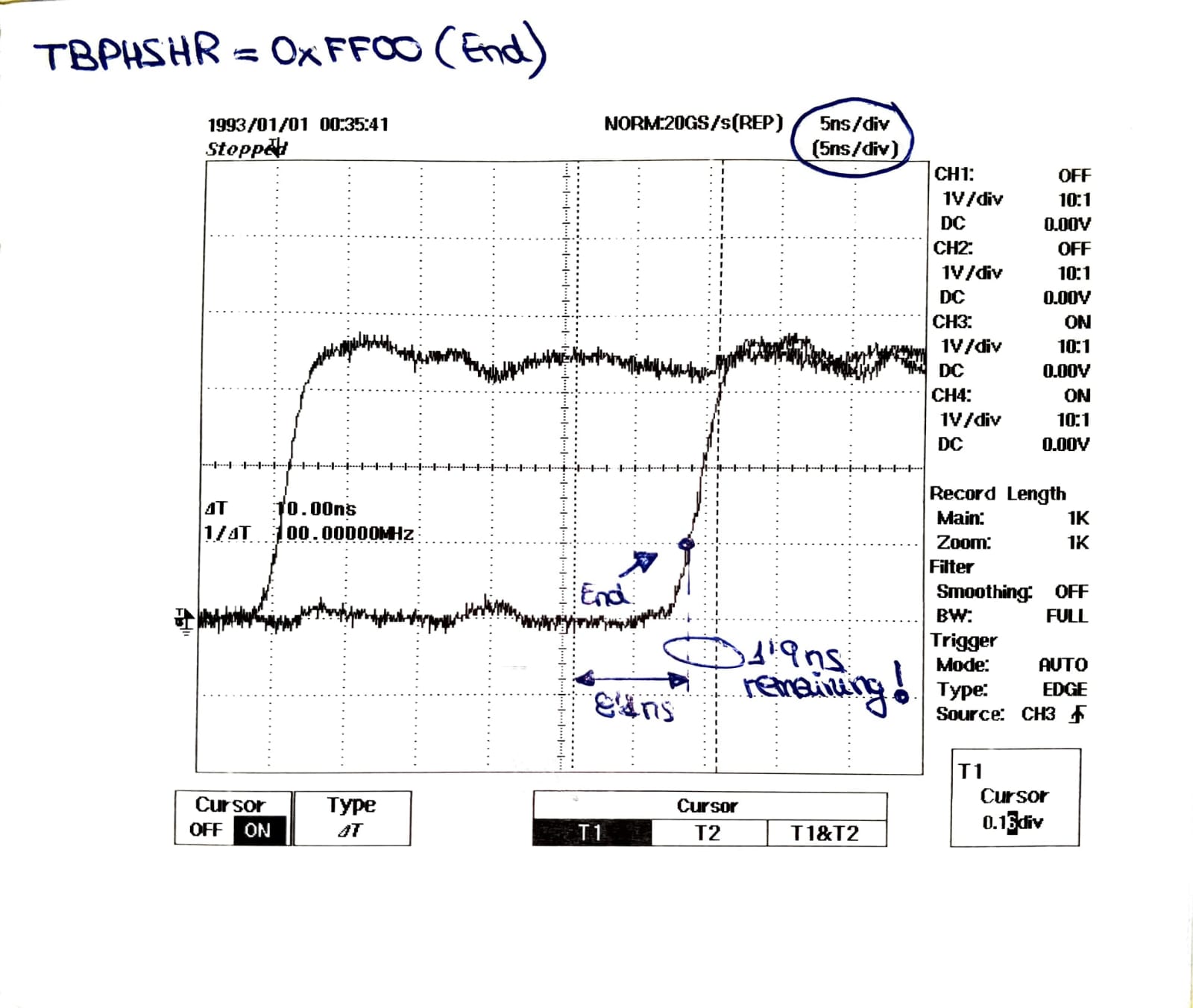
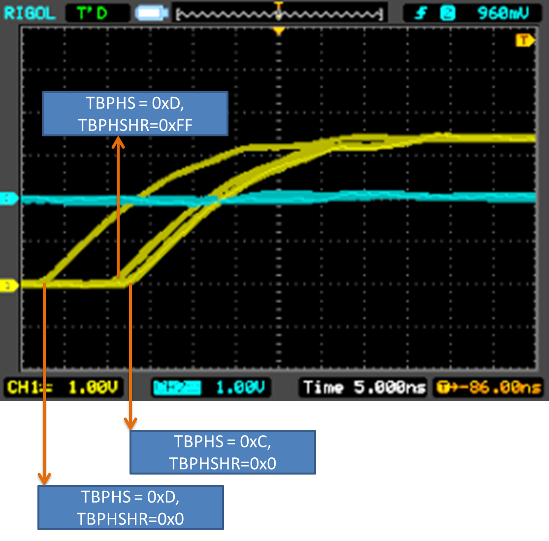
    First I tried to write in the register TBPHSHR = 0xFF00 which is equivalent to 65280 in decimal. By doing this I have achieved that the PWM signal I am monitoring moves 8.1ns from the 10ns I expected it to move. I have attached 3 captures of the oscilloscope for you to see what I mean and the capture of the xxpressions in CCS.

    Doing this I can not sweep the whole range of 10ns which is each of the 1000 steps of the PWM signal, I would miss 1.9 ns.

    I also want to ask you something else: Why should I get to 0xFF00 in the TBPHSHR register if the SFO library really returns a MEP_ScaleFactor = 66? Doesn't this mean that each of the steps of the PWM is divided in 66 microsteps of 150 ps?
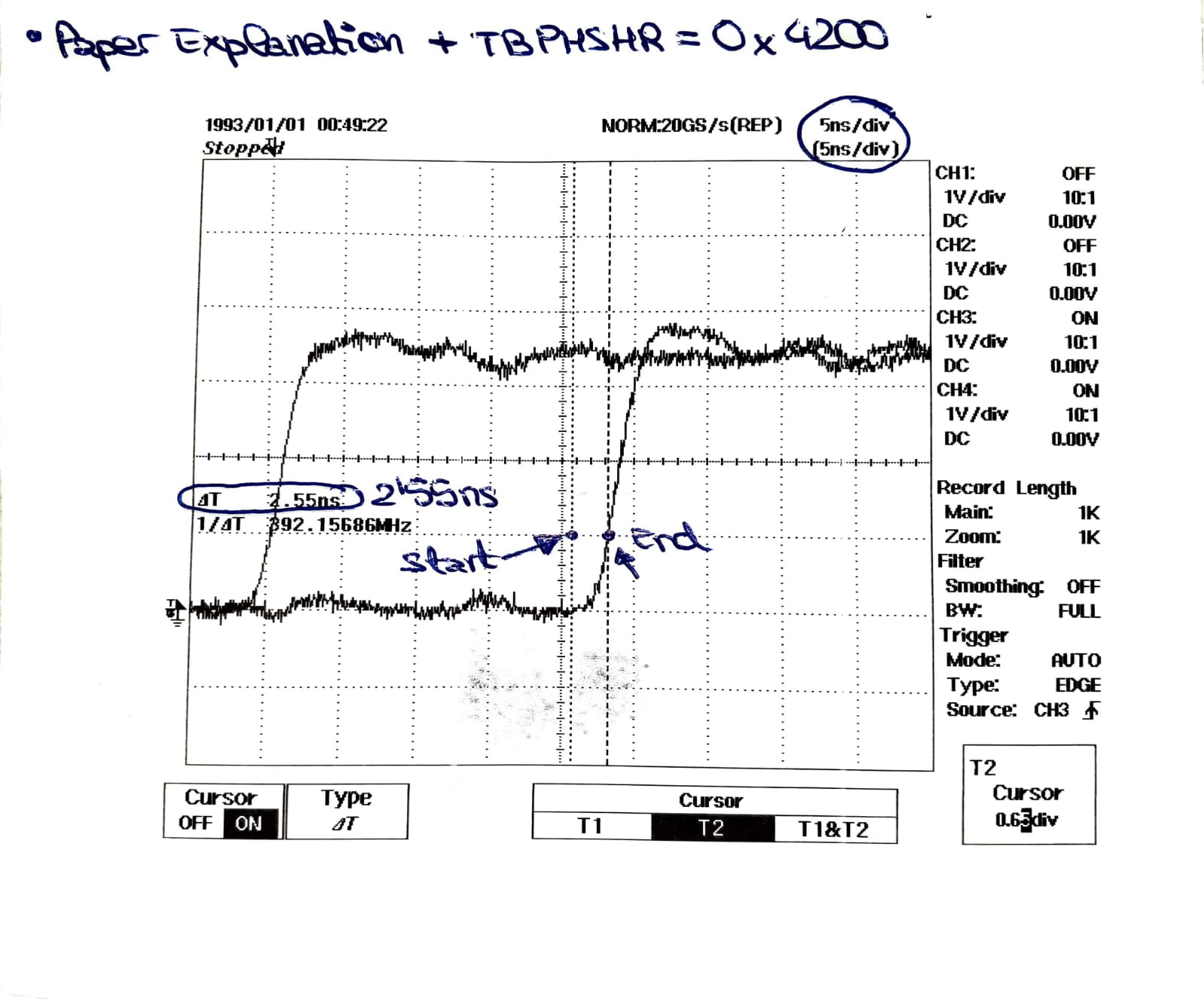
    According to my way of understanding it: 10ns = 66 micro-steps * 150ps for each micro-step and therefore, if I write in the register TBPHSHR = 0x4200 (66 in decimal) it should move 10ns and what I get is that it moves 2.55ns (which leads me to think that the resolution is not 150ps but 2.55ns/66 steps = 38ns for each micro-step instead of 150ps). I attach an explanation of my way of understanding it and a capture of the oscilloscope testing this that I have mentioned.

    I hope that now that I have detailed a little more my explanation and problem you can see what I am doing wrong or that I am understanding in a wrong way. Greetings. Iulian

  • Iulian,

    Thank you for your detialed explanation. When you enable the AUTOCONV, the HRPWM module internally will use the MEP_SCALEFACTOR and apply it in the calculation equations internally. If the AUTOCONV wasnt on, then yes, 0-66 would be the complete placement. If the AUTOCONV is on, then internally 0-FF gets translated to a number between 0-66. Linear transformation to ease your calcualtion.

    As far as the missing 2.5 ns, how about we leave AUTOCONV off, and we sweep the values, and go a bit past 66? Would that cover the rest of the range?

    Maybe try 70? 75? and capture some scope shots for me to review. Make sure to leave autoconv off.

    Nima

  • Hi Nima, thanks for your answer.

    Your answer about self-conversion and the MEP_ScaleFactor has cleared up quite a few questions for me.
    In response to what you told me, I have done several tests with the LAUNCHXL-F280049C. First of all I want to clarify "my setup":
    I have a 1GHz HD oscilloscope, I have calibrated the 4 probes (passive) and I have checked that the PWM "slave" signals are synchronized between them (error -+80pS) which is more than acceptable. To measure the phase shift between 2 slaves I used a built-in oscilloscope function that measures the time skew between 2 signals by averaging 100 samples of the " time skew " (and I used the maximum full scale time to increase the accuracy).
    Having said that, I have now done two tests. One with the register (AUTOCONV = 1) and another with the register (AUTOCONV = 0 & MEP_STEPS = 66).

    -AUTOCONV CASE = 1 -->
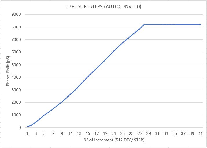
    I have performed a sweep for the register (EPwm2Regs.TBPHS.TBPHSHR) from 0x0000 to 0xFF00 using steps of 0x0A00 (In DEC in increments of 2560). I have collected this data in an Excel and proceeded to graph the results. It can be seen that when reaching EPwm2Regs.TBPHS.TBPHSHR = 0xDC00 the EPWM2_A signal stops moving, stagnating at 8.15 ns with respect to EPWM3_A.Even if you go up to EPwm2Regs.TBPHS.TBPHSHR = 0xFF00 the phase shift stays at 8.15 ns.


    -CASE AUTOCONV = 0 & MEP_STEP = 66 -->
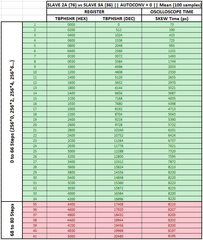
    I have performed a sweep for the register (EPwm2Regs.TBPHS.TBPHSHR) from 0x0000 to 0x4200 (which corresponds to the 66 steps of the MEP 256*66 = 16896 == 0x4200)
    In the same way as for the case where AUTOCONV = 1, from 0x3600 the PWM signal is stagnant and the phase shift remains close to 8.22 ns. As you have asked me to do, I have increased the steps above 66 to 80. The result is that the phase shift has been maintained at 8.2 ns. A remarkable fact is that when I reach 150 the PWM signal I am shifting suffers a glitch after the rise time producing a valley.

    I am attaching captures of the data collected for both tests in Excel and the glitch that suffers the PWM signal when AUTOCONV = 0 and I try to write EPwm2Regs.TBPHS.TBPHSHR = 0x9600 (38400 DEC == 256*150).

  • Thats great. I see everything now in your data.

    So we are still not able to do a FULL sweep correct?

  • No, I am not yet able to obtain a phase shift greater than 8.2ns using only the High-Resolution register. This is putting in serious risk the project of the converter since it is a control with 16'66 times less precision (since I can only make fine steps of 2'5ns not to fall in the gap that I do not reach between the 8.2 and 10ns of the PWM step)

    I have tried to initialize PWMs in many different ways and I think I have read all the posts related to this topic that I have found in your activity but I always come to the same conclusion: Whether I activate AUTOCONV or if it is deactivated I can not overcome the 8.2ns of phase shift.

    Do you have any idea what I should configure or where is the error I am making?

    I wait for your answer. Thank you.

  • Can you compare your configuration with the one here:

    C2000Ware_3_03_00_00\device_support\f2837xd\examples\cpu1\hrpwm_deadband_sfo_v8

  • I have reviewed the example in question and I would say that I perform the same initialization (with the distinction that I use driverlib and in this example I access records).

    I'm not clear what the GLDCTL record is for. In my configuration I don't have anything configured about this register and I don't have implemented any deadband either.

    For the PWM Master:
    - Count Up-Down
    - Phase shift off
    - Shadow of the Compare: MUST BE CTR=(ZER & PRD)
    - EPWM_SYNC_OUT_PULSE_ON_COUNTER_ZERO to generate the synchronization pulse for the Slaves.
    - HR_EdgeSelect = up and down.
    -HR Control mode: Phase Control
    - HR shadow comparison: MUST BE CTR=(ZER & PRD)
    - Activate auto conversion
    - Deactivate high-resolution period control

    For PWM Slaves:
    - Count Up-Down
    - Phase shift activated
    - Shadow of the Compare: MUST BE CTR=(ZER & PRD)
    - EPWM_SYNC_OUT_PULSE_ON_EPWMxSYNCIN to synchronize with the master
    - HR_EdgeSelect = up and down.
    - HR Control mode: Phase Control
    - HR shadow comparison: MUST BE CTR=(ZER & PRD)
    - Activate auto conversion
    - Deactivate high-resolution period control
    - Activate high-resolution phase shift.

    I attach my initialization code. On one hand I have the PWM Master and in the loop I initialize the other PWM.

    // In the Main Setup()
    init_ePWM_GPIOs();
    EALLOW;
    SysCtl_disablePeripheral(SYSCTL_PERIPH_CLK_TBCLKSYNC);
    init_HR_EPWM ();
    SysCtl_enablePeripheral(SYSCTL_PERIPH_CLK_TBCLKSYNC);
    EDIS;
    
    //The Configuration function
    void init_HR_EPWM (void){
    
        //----------------------------------------------------------------------> PWM
    //    EPWM_setEmulationMode(EPWM1_BASE, EPWM_EMULATION_FREE_RUN);
    
        EPWM_setTimeBasePeriod(EPWM1_BASE, EPWM_PERIOD);
        EPWM_setTimeBaseCounter(EPWM1_BASE, 0U);
    
        EPWM_setCounterCompareValue(EPWM1_BASE, EPWM_COUNTER_COMPARE_A, EPWM_DUTY);
    
        EPWM_setTimeBaseCounterMode(EPWM1_BASE, EPWM_COUNTER_MODE_UP_DOWN);
        EPWM_disablePhaseShiftLoad(EPWM1_BASE);
        EPWM_setClockPrescaler(EPWM1_BASE, EPWM_CLOCK_DIVIDER_1, EPWM_HSCLOCK_DIVIDER_1);
    
        EPWM_setCounterCompareShadowLoadMode(EPWM1_BASE, EPWM_COUNTER_COMPARE_A, EPWM_COMP_LOAD_ON_CNTR_ZERO_PERIOD);
    
        EPWM_setActionQualifierAction(EPWM1_BASE, EPWM_AQ_OUTPUT_A, EPWM_AQ_OUTPUT_HIGH, EPWM_AQ_OUTPUT_ON_TIMEBASE_ZERO);
        EPWM_setActionQualifierAction(EPWM1_BASE, EPWM_AQ_OUTPUT_A, EPWM_AQ_OUTPUT_LOW, EPWM_AQ_OUTPUT_ON_TIMEBASE_PERIOD);
    
        EPWM_setSyncOutPulseMode(EPWM1_BASE, EPWM_SYNC_OUT_PULSE_ON_COUNTER_ZERO); //Counter zero event generates EPWM sync-out pulse
    
    //    EPWM_selectPeriodLoadEvent(EPWM1_BASE, EPWM_SHADOW_LOAD_MODE_SYNC);
        EPWM_setInterruptSource(EPWM1_BASE, EPWM_INT_TBCTR_ZERO);
        EPWM_enableInterrupt(EPWM1_BASE);
        EPWM_setInterruptEventCount(EPWM1_BASE, 1U);
        //----------------------------------------------
    
        //----------------------------------------------------------------------> HRPWM
        HRPWM_setMEPEdgeSelect(EPWM1_BASE, HRPWM_CHANNEL_A, HRPWM_MEP_CTRL_RISING_AND_FALLING_EDGE); //MEP controls both rising and falling edge
        HRPWM_setMEPControlMode(EPWM1_BASE, HRPWM_CHANNEL_A, HRPWM_MEP_PHASE_CTRL); //TBPHSHR controls MEP edge
        HRPWM_setCounterCompareShadowLoadEvent(EPWM1_BASE, HRPWM_CHANNEL_A, HRPWM_LOAD_ON_CNTR_ZERO);         // MUST BE CTR=(ZER & PRD)
    
        HRPWM_enableAutoConversion(EPWM1_BASE);
    //    HRPWM_disableAutoConversion(EPWM1_BASE);
    //    HRPWM_setMEPStep(EPWM1_BASE, 66U);
    
        HRPWM_disablePeriodControl(EPWM1_BASE); //Disable high resolution period feature
        HRPWM_setSyncPulseSource(EPWM1_BASE, HRPWM_PWMSYNC_SOURCE_PERIOD);
        //----------------------------------------------
    
    
        uint16_t j = 0;
        for(j=2 ; j<7 ; j++){
            //----------------------------------------------------------------------> PWM
    //        EPWM_setEmulationMode(ePWM[j], EPWM_EMULATION_FREE_RUN);
    
            EPWM_setTimeBasePeriod(ePWM[j], EPWM_PERIOD);
            EPWM_setPhaseShift(ePWM[j], 0U);
            EPWM_setTimeBaseCounter(ePWM[j], 0U);
    
            EPWM_setCounterCompareValue(ePWM[j], EPWM_COUNTER_COMPARE_A, EPWM_DUTY);
    
            EPWM_setTimeBaseCounterMode(ePWM[j], EPWM_COUNTER_MODE_UP_DOWN);
            EPWM_enablePhaseShiftLoad(ePWM[j]);
            EPWM_setClockPrescaler(ePWM[j], EPWM_CLOCK_DIVIDER_1, EPWM_HSCLOCK_DIVIDER_1);
    
            EPWM_setCounterCompareShadowLoadMode(ePWM[j], EPWM_COUNTER_COMPARE_A, EPWM_COMP_LOAD_ON_CNTR_ZERO_PERIOD);
            EPWM_setCounterCompareShadowLoadMode(ePWM[j], EPWM_COUNTER_COMPARE_B, EPWM_COMP_LOAD_ON_CNTR_ZERO_PERIOD);
            EPWM_setSyncOutPulseMode(ePWM[j], EPWM_SYNC_OUT_PULSE_ON_EPWMxSYNCIN);
    
            EPWM_setActionQualifierAction(ePWM[j], EPWM_AQ_OUTPUT_A, EPWM_AQ_OUTPUT_HIGH, EPWM_AQ_OUTPUT_ON_TIMEBASE_ZERO);
            EPWM_setActionQualifierAction(ePWM[j], EPWM_AQ_OUTPUT_A, EPWM_AQ_OUTPUT_LOW, EPWM_COMP_LOAD_ON_CNTR_ZERO_PERIOD);
            EPWM_setActionQualifierAction(ePWM[j], EPWM_AQ_OUTPUT_B, EPWM_AQ_OUTPUT_LOW, EPWM_AQ_OUTPUT_ON_TIMEBASE_ZERO);
            EPWM_setActionQualifierAction(ePWM[j], EPWM_AQ_OUTPUT_B, EPWM_AQ_OUTPUT_HIGH, EPWM_COMP_LOAD_ON_CNTR_ZERO_PERIOD);
            //----------------------------------------------
    
            //----------------------------------------------------------------------> HRPWM
            HRPWM_setMEPEdgeSelect(ePWM[j], HRPWM_CHANNEL_A, HRPWM_MEP_CTRL_RISING_AND_FALLING_EDGE); //MEP controls both rising and falling edge
            HRPWM_setMEPControlMode(ePWM[j], HRPWM_CHANNEL_A, HRPWM_MEP_PHASE_CTRL); //TBPHSHR controls MEP edge
            HRPWM_setCounterCompareShadowLoadEvent(ePWM[j], HRPWM_CHANNEL_A, HRPWM_LOAD_ON_CNTR_ZERO);         // MUST BE CTR=(ZER & PRD)
    
            HRPWM_setMEPEdgeSelect(ePWM[j], HRPWM_CHANNEL_B, HRPWM_MEP_CTRL_RISING_AND_FALLING_EDGE); //MEP controls both rising and falling edge
            HRPWM_setMEPControlMode(ePWM[j], HRPWM_CHANNEL_B, HRPWM_MEP_PHASE_CTRL); //TBPHSHR controls MEP edge
            HRPWM_setCounterCompareShadowLoadEvent(ePWM[j], HRPWM_CHANNEL_B, HRPWM_LOAD_ON_CNTR_ZERO);         // MUST BE CTR=(ZER & PRD)
    
            HRPWM_enableAutoConversion(ePWM[j]);
    //        HRPWM_disableAutoConversion(ePWM[j]);
    //        HRPWM_setMEPStep(ePWM[j], 66U);
    
    
            HRPWM_disablePeriodControl(ePWM[j]); //Disable high resolution period feature
            HRPWM_enablePhaseShiftLoad(ePWM[j]); //Enable high resolution phase load
            HRPWM_setSyncPulseSource(ePWM[j], HRPWM_PWMSYNC_SOURCE_PERIOD);
            //--------------------------------------------------------------------------------------------
    
        }
    
        //-------------------------------------> ePWM Synchronization <------------------------------------
        //----------------------------------------------
    
        SysCtl_setSyncInputConfig(SYSCTL_SYNC_IN_EPWM4, SYSCTL_SYNC_IN_SRC_EPWM1SYNCOUT);
        SysCtl_setSyncInputConfig(SYSCTL_SYNC_IN_EPWM7, SYSCTL_SYNC_IN_SRC_EPWM1SYNCOUT);
    }

  • Hi Nima, I´ve been trying some more PWM initializations unsuccessfully.

    Could you try to generate a simple program based on Driverlib for F280049C or similar and try to introduce a high resolution phase shift between a Master PWM signal and a slave (Trying to achieve the HR whole range of EPwm2Regs.TBPHS.TBPHSHR --> 0x0000 to 0xFF00 with AUTOCONV = 1).

    I am attaching my CCS project in case it helps to find the error that does not allow to reach the whole range of a PWM step with the high resolution register.

    I wait for your answer, greetings, Iulian..

    F28004x_Control_Design.zip

  • Iulian,

    Yes I can definitely work on putting some code together as I'm not sure what is causing this, however it will take some days.

    I will respond back once I have some results. In the meantime if it takes a long time, I will keep you up-to-date with the progress.

    Nima

  • Iulian,

    Still working on putting this together for you.

    Nima

  • Okay Iulian, I am seeing similar things. I just cant seem to get the HR portion to sweep the whole range.

    , , and

    I require some help on this one. Here is all the info to know the problem.

    Two EPWM's are synchronized in HR mode (TBPHS and TBPHSHR). Auto-convert is enabled. The TBPHSHR going from 0-FF cannot cover the whole range of an EPWM coarse step.

    Below is an example of the issue. The 0xFF doesnt fully sweep...

    Here is the EPWM setting:

    void initEPWM(uint32_t base)
    {
        //
        // Set-up TBCLK
        //
        EPWM_setTimeBasePeriod(base, EPWM_TIMER_TBPRD);
        EPWM_setPhaseShift(base, 0U);
        EPWM_setTimeBaseCounter(base, 0U);
    
        //
        // Set Compare values
        //
        EPWM_setCounterCompareValue(base,
                                    EPWM_COUNTER_COMPARE_A,
                                    EPWM_TIMER_TBPRD/2);
        EPWM_setCounterCompareValue(base,
                                    EPWM_COUNTER_COMPARE_B,
                                    EPWM_TIMER_TBPRD/4);
    
        //
        // Set up counter mode
        //
        EPWM_setTimeBaseCounterMode(base, EPWM_COUNTER_MODE_UP);
        EPWM_disablePhaseShiftLoad(base);
        EPWM_setClockPrescaler(base,
                               EPWM_CLOCK_DIVIDER_1,
                               EPWM_HSCLOCK_DIVIDER_1);
    
        //
        // Set up shadowing
        //
        EPWM_setCounterCompareShadowLoadMode(base,
                                             EPWM_COUNTER_COMPARE_A,
                                             EPWM_COMP_LOAD_ON_CNTR_ZERO);
        EPWM_setCounterCompareShadowLoadMode(base,
                                             EPWM_COUNTER_COMPARE_B,
                                             EPWM_COMP_LOAD_ON_CNTR_ZERO);
    
        //
        // Set actions
        //
        EPWM_setActionQualifierAction(base,
                                      EPWM_AQ_OUTPUT_A,
                                      EPWM_AQ_OUTPUT_HIGH,
                                      EPWM_AQ_OUTPUT_ON_TIMEBASE_ZERO);
        EPWM_setActionQualifierAction(base,
                                      EPWM_AQ_OUTPUT_B,
                                      EPWM_AQ_OUTPUT_HIGH,
                                      EPWM_AQ_OUTPUT_ON_TIMEBASE_ZERO);
        EPWM_setActionQualifierAction(base,
                                      EPWM_AQ_OUTPUT_A,
                                      EPWM_AQ_OUTPUT_LOW,
                                      EPWM_AQ_OUTPUT_ON_TIMEBASE_UP_CMPA);
        EPWM_setActionQualifierAction(base,
                                      EPWM_AQ_OUTPUT_B,
                                      EPWM_AQ_OUTPUT_LOW,
                                      EPWM_AQ_OUTPUT_ON_TIMEBASE_UP_CMPB);
    
    
        HRPWM_setMEPEdgeSelect(base, HRPWM_CHANNEL_A, HRPWM_MEP_CTRL_RISING_AND_FALLING_EDGE);
        HRPWM_setMEPControlMode(base, HRPWM_CHANNEL_A, HRPWM_MEP_PHASE_CTRL);
        HRPWM_setCounterCompareShadowLoadEvent(base, HRPWM_CHANNEL_A, HRPWM_LOAD_ON_CNTR_ZERO_PERIOD);
    
        HRPWM_setMEPEdgeSelect(base, HRPWM_CHANNEL_B, HRPWM_MEP_CTRL_RISING_AND_FALLING_EDGE);
        HRPWM_setMEPControlMode(base, HRPWM_CHANNEL_B, HRPWM_MEP_PHASE_CTRL);
        HRPWM_setCounterCompareShadowLoadEvent(base, HRPWM_CHANNEL_B, HRPWM_LOAD_ON_CNTR_ZERO_PERIOD);
    
        HRPWM_enableAutoConversion(base);
    
        HRPWM_enablePhaseShiftLoad(base);
    
        //
        // Interrupt where we will change the Compare Values
        // Select INT on Time base counter zero event,
        // Enable INT, generate INT on 1rd event
        //
        EPWM_setInterruptSource(base, EPWM_INT_TBCTR_ZERO);
        EPWM_enableInterrupt(base);
        EPWM_setInterruptEventCount(base, 1U);
    }

    NO HR PERIOD or DUTY.

    Do you know what causes that? This is not a unique case, I cant seem to get a full sweep in any mode.

  •  Do you know why the TBPHSHR doesnt sweep the range of a full EPWMCLK step?

  • Hi Nima, excuse the delay in answering.
    These days I have made some progress and I think I have achieved a phase shift of one coarse step of the PWM with the full range of the TBPHSHR register with AUTOCONV = 1.
    In my project I am using the internal oscillator INTOSC2 to generate the CLK signal. I have configured the PLL multipliers as follows:

    #define DEVICE_OSCSRC_FREQ 10000000U
    
    #define DEVICE_SETCLOCK_CFG (SYSCTL_OSCSRC_OSC2 | SYSCTL_IMULT(10) |
                                         SYSCTL_FMULT_NONE | SYSCTL_SYSDIV(2) \
                                         SYSCTL_PLL_ENABLE)
    
    #define DEVICE_SYSCLK_FREQ ((DEVICE_OSCSRC_FREQ * 10 * 1) / 2)

    Starting from this PLL configuration I have generated an initialization function of all PWM modules I need synchronizing them with ePWM_1. I have a difference with the code you passed me in your answer:

    --> I see that you have initialized the TBCTR of the PWM modules in "UP-Mode". In several of your posts I have seen that you always recommend initializing it in "UP-DOWN-Mode". I have it initialized like that and it has worked.
    With this configuration of the PLL you can get a 20ns resolution of the PWM and I think I could make a phase shift of a whole step of 20ns by increasing the TBPHSHR between 2 slaves. I'm going to do some more tests to rule out a mistake in my previous tests.

    Could you try this PLL configuration, change the PWM counting mode and try to get a 100 kHz signal?

    The code I used is the one from my previous post, I only played with the internal crystal and the PLL of the microcontroller.

    I hope that with these two changes you can see something and clarify what is happening.

  • Hi again,

    I've been doing a number of trials since I didn't get the 20ns sweep with the high resolution registers. I'm going to attach my code form my current PWM modules initialization so you can follow my explanation of what I've discovered in case you have any idea what's causing it.

    //------------------------------------------------------------------------------------------- PWM CONFIGURATION
    void init_HR_EPWM (void){
    ///////////////////////////////////////////////////////////////////////////////
    //----------------------------------------------------------------------> PWM
    ///////////////////////////////////////////////////////////////////////////////
    //---------------------------------------------- PERIOD CONFIGURATION -->
    EPWM_setTimeBasePeriod(EPWM1_BASE, EPWM_PERIOD);
    EPWM_setPeriodLoadMode(EPWM1_BASE, EPWM_PERIOD_SHADOW_LOAD);
    EPWM_selectPeriodLoadEvent(EPWM1_BASE, EPWM_SHADOW_LOAD_MODE_COUNTER_ZERO);

    //---------------------------------------------- TB_COUNTER CONFIGURATION -->
    EPWM_setTimeBaseCounter(EPWM1_BASE, 0U);
    EPWM_setTimeBaseCounterMode(EPWM1_BASE, EPWM_COUNTER_MODE_UP_DOWN);

    //---------------------------------------------- COMPARE A/B CONFIGURATION -->
    EPWM_setCounterCompareValue(EPWM1_BASE, EPWM_COUNTER_COMPARE_A, EPWM_PERIOD/2);
    EPWM_setCounterCompareValue(EPWM1_BASE, EPWM_COUNTER_COMPARE_B, EPWM_PERIOD - EPWM_PERIOD/2);
    EPWM_setCounterCompareShadowLoadMode(EPWM1_BASE, EPWM_COUNTER_COMPARE_A, EPWM_COMP_LOAD_ON_CNTR_ZERO);
    EPWM_setCounterCompareShadowLoadMode(EPWM1_BASE, EPWM_COUNTER_COMPARE_B, EPWM_COMP_LOAD_ON_CNTR_ZERO);

    //---------------------------------------------- PHASE_SHIFT CONFIGURATION -->
    EPWM_disablePhaseShiftLoad(EPWM1_BASE);

    //---------------------------------------------- CLOCK PRESCALER CONFIGURATION -->
    EPWM_setClockPrescaler(EPWM1_BASE, EPWM_CLOCK_DIVIDER_1, EPWM_HSCLOCK_DIVIDER_1);

    //---------------------------------------------- OUTPUT CONFIGURATION -->
    EPWM_setActionQualifierAction(EPWM1_BASE, EPWM_AQ_OUTPUT_A, EPWM_AQ_OUTPUT_HIGH, EPWM_AQ_OUTPUT_ON_TIMEBASE_ZERO);
    EPWM_setActionQualifierAction(EPWM1_BASE, EPWM_AQ_OUTPUT_A, EPWM_AQ_OUTPUT_LOW, EPWM_AQ_OUTPUT_ON_TIMEBASE_UP_CMPA);
    EPWM_setActionQualifierAction(EPWM1_BASE, EPWM_AQ_OUTPUT_A, EPWM_AQ_OUTPUT_HIGH, EPWM_AQ_OUTPUT_ON_TIMEBASE_PERIOD);
    EPWM_setActionQualifierAction(EPWM1_BASE, EPWM_AQ_OUTPUT_A, EPWM_AQ_OUTPUT_LOW, EPWM_AQ_OUTPUT_ON_TIMEBASE_DOWN_CMPB);

    //---------------------------------------------- SYNCRO CONFIGURATION -->
    EPWM_setSyncOutPulseMode(EPWM1_BASE, EPWM_SYNC_OUT_PULSE_ON_COUNTER_ZERO);
    // EPWM_setCountModeAfterSync(EPWM1_BASE, EPWM_COUNT_MODE_UP_AFTER_SYNC);
    EPWM_forceSyncPulse(EPWM1_BASE);

    //---------------------------------------------- GLOBAL LOAD CONFIGURATION -->
    EPWM_setGlobalLoadTrigger(EPWM1_BASE, EPWM_GL_LOAD_PULSE_CNTR_ZERO_PERIOD);
    EPWM_enableGlobalLoadOneShotMode(EPWM1_BASE);
    EPWM_enableGlobalLoad(EPWM1_BASE);
    EPWM_setupEPWMLinks(EPWM1_BASE, EPWM_LINK_WITH_EPWM_1, EPWM_LINK_GLDCTL2);

    //---------------------------------------------- PWM INTERRUPT CONFIGURATION -->
    // EPWM_setInterruptSource(EPWM1_BASE, EPWM_INT_TBCTR_ZERO);
    // EPWM_enableInterrupt(EPWM1_BASE);
    // EPWM_setInterruptEventCount(EPWM1_BASE, 1U);

    ///////////////////////////////////////////////////////////////////////////////
    //--------------------------------------------------------------------> HRPWM
    ///////////////////////////////////////////////////////////////////////////////
    //---------------------------------------------- HR-EDGE CONFIGURATION -->
    HRPWM_setMEPEdgeSelect(EPWM1_BASE, HRPWM_CHANNEL_A, HRPWM_MEP_CTRL_RISING_AND_FALLING_EDGE);

    //---------------------------------------------- HR-CONTROL CONFIGURATION -->
    HRPWM_setMEPControlMode(EPWM1_BASE, HRPWM_CHANNEL_A, HRPWM_MEP_PHASE_CTRL);
    HRPWM_disablePhaseShiftLoad(EPWM1_BASE);
    HRPWM_enablePeriodControl(EPWM1_BASE);

    //---------------------------------------------- HR-COMPARE CONFIGURATION -->
    HRPWM_setCounterCompareShadowLoadEvent(EPWM1_BASE, HRPWM_CHANNEL_A, HRPWM_LOAD_ON_CNTR_ZERO_PERIOD);

    //---------------------------------------------- HR-MEP_SCALEFACTOR CONFIGURATION -->
    HRPWM_enableAutoConversion(EPWM1_BASE);
    // HRPWM_disableAutoConversion(EPWM1_BASE);
    // HRPWM_setMEPStep(EPWM1_BASE, 66U);

    //---------------------------------------------- HR-SYNCRO CONFIGURATION -->
    HRPWM_setSyncPulseSource(EPWM1_BASE, HRPWM_PWMSYNC_SOURCE_ZERO);
    //----------------------------------------------


    uint16_t j = 0;
    for(j=2 ; j<7 ; j++){
    ///////////////////////////////////////////////////////////////////////////////
    //----------------------------------------------------------------------> PWM
    ///////////////////////////////////////////////////////////////////////////////
    //---------------------------------------------- PERIOD CONFIGURATION -->
    EPWM_setTimeBasePeriod(ePWM[j], EPWM_PERIOD);
    EPWM_setPeriodLoadMode(ePWM[j], EPWM_PERIOD_SHADOW_LOAD);
    EPWM_selectPeriodLoadEvent(ePWM[j], EPWM_SHADOW_LOAD_MODE_COUNTER_ZERO);

    //---------------------------------------------- TB_COUNTER CONFIGURATION -->
    EPWM_setTimeBaseCounter(ePWM[j], 0U);
    EPWM_setTimeBaseCounterMode(ePWM[j], EPWM_COUNTER_MODE_UP_DOWN);

    //---------------------------------------------- COMPARE A/B CONFIGURATION -->
    EPWM_setCounterCompareValue(ePWM[j], EPWM_COUNTER_COMPARE_A, EPWM_PERIOD/2);
    EPWM_setCounterCompareValue(ePWM[j], EPWM_COUNTER_COMPARE_B, EPWM_PERIOD - EPWM_PERIOD/2);
    EPWM_setCounterCompareShadowLoadMode(ePWM[j], EPWM_COUNTER_COMPARE_A, EPWM_COMP_LOAD_ON_CNTR_ZERO);
    EPWM_setCounterCompareShadowLoadMode(ePWM[j], EPWM_COUNTER_COMPARE_B, EPWM_COMP_LOAD_ON_CNTR_ZERO);

    //---------------------------------------------- PHASE_SHIFT CONFIGURATION -->
    EPWM_enablePhaseShiftLoad(ePWM[j]);
    EPWM_setPhaseShift(ePWM[j], 0U);

    //---------------------------------------------- CLOCK PRESCALER CONFIGURATION -->
    EPWM_setClockPrescaler(ePWM[j], EPWM_CLOCK_DIVIDER_1, EPWM_HSCLOCK_DIVIDER_1);

    //---------------------------------------------- OUTPUT CONFIGURATION -->
    EPWM_setActionQualifierAction(ePWM[j], EPWM_AQ_OUTPUT_A, EPWM_AQ_OUTPUT_HIGH, EPWM_AQ_OUTPUT_ON_TIMEBASE_ZERO);
    EPWM_setActionQualifierAction(ePWM[j], EPWM_AQ_OUTPUT_A, EPWM_AQ_OUTPUT_LOW, EPWM_AQ_OUTPUT_ON_TIMEBASE_UP_CMPA);
    EPWM_setActionQualifierAction(ePWM[j], EPWM_AQ_OUTPUT_A, EPWM_AQ_OUTPUT_HIGH, EPWM_AQ_OUTPUT_ON_TIMEBASE_PERIOD);
    EPWM_setActionQualifierAction(ePWM[j], EPWM_AQ_OUTPUT_A, EPWM_AQ_OUTPUT_LOW, EPWM_AQ_OUTPUT_ON_TIMEBASE_DOWN_CMPB);

    EPWM_setActionQualifierAction(ePWM[j], EPWM_AQ_OUTPUT_B, EPWM_AQ_OUTPUT_LOW, EPWM_AQ_OUTPUT_ON_TIMEBASE_ZERO);
    EPWM_setActionQualifierAction(ePWM[j], EPWM_AQ_OUTPUT_B, EPWM_AQ_OUTPUT_HIGH, EPWM_AQ_OUTPUT_ON_TIMEBASE_UP_CMPA);
    EPWM_setActionQualifierAction(ePWM[j], EPWM_AQ_OUTPUT_B, EPWM_AQ_OUTPUT_LOW, EPWM_AQ_OUTPUT_ON_TIMEBASE_PERIOD);
    EPWM_setActionQualifierAction(ePWM[j], EPWM_AQ_OUTPUT_B, EPWM_AQ_OUTPUT_HIGH, EPWM_AQ_OUTPUT_ON_TIMEBASE_DOWN_CMPB);

    //---------------------------------------------- SYNCRO CONFIGURATION -->
    EPWM_setSyncOutPulseMode(ePWM[j], EPWM_SYNC_OUT_PULSE_ON_EPWMxSYNCIN);
    // EPWM_setCountModeAfterSync(ePWM[j], EPWM_COUNT_MODE_UP_AFTER_SYNC);
    EPWM_forceSyncPulse(ePWM[j]);

    //---------------------------------------------- GLOBAL LOAD CONFIGURATION -->
    EPWM_setGlobalLoadTrigger(ePWM[j], EPWM_GL_LOAD_PULSE_CNTR_ZERO_PERIOD);
    EPWM_enableGlobalLoadOneShotMode(ePWM[j]);
    EPWM_enableGlobalLoad(ePWM[j]);
    EPWM_setupEPWMLinks(ePWM[j], EPWM_LINK_WITH_EPWM_1, EPWM_LINK_GLDCTL2);
    //----------------------------------------------

    ///////////////////////////////////////////////////////////////////////////////
    //----------------------------------------------------------------------> HRPWM
    ///////////////////////////////////////////////////////////////////////////////
    //---------------------------------------------- HR-EDGE CONFIGURATION -->
    HRPWM_setMEPEdgeSelect(ePWM[j], HRPWM_CHANNEL_A, HRPWM_MEP_CTRL_RISING_AND_FALLING_EDGE);
    HRPWM_setMEPEdgeSelect(ePWM[j], HRPWM_CHANNEL_B, HRPWM_MEP_CTRL_RISING_AND_FALLING_EDGE);

    //---------------------------------------------- HR-CONTROL CONFIGURATION -->
    HRPWM_setMEPControlMode(ePWM[j], HRPWM_CHANNEL_A, HRPWM_MEP_PHASE_CTRL);
    HRPWM_setMEPControlMode(ePWM[j], HRPWM_CHANNEL_B, HRPWM_MEP_PHASE_CTRL);
    HRPWM_enablePhaseShiftLoad(ePWM[j]);
    HRPWM_disablePeriodControl(ePWM[j]);

    //---------------------------------------------- HR-COMPARE CONFIGURATION -->
    HRPWM_setCounterCompareShadowLoadEvent(ePWM[j], HRPWM_CHANNEL_A, HRPWM_LOAD_ON_CNTR_ZERO_PERIOD);
    HRPWM_setCounterCompareShadowLoadEvent(ePWM[j], HRPWM_CHANNEL_B, HRPWM_LOAD_ON_CNTR_ZERO_PERIOD);

    //---------------------------------------------- HR-MEP_SCALEFACTOR CONFIGURATION -->
    HRPWM_enableAutoConversion(ePWM[j]);
    // HRPWM_disableAutoConversion(ePWM[j]);
    // HRPWM_setMEPStep(ePWM[j], 66U);

    //---------------------------------------------- HR-SYNCRO CONFIGURATION -->
    HRPWM_setSyncPulseSource(ePWM[j], HRPWM_PWMSYNC_SOURCE_ZERO);
    //--------------------------------------------------------------------------------------------

    }

    //-------------------------------------> ePWM Synchronization Chain <------------------------------------
    //----------------------------------------------
    SysCtl_setSyncInputConfig(SYSCTL_SYNC_IN_EPWM4, SYSCTL_SYNC_IN_SRC_EPWM1SYNCOUT);
    SysCtl_setSyncInputConfig(SYSCTL_SYNC_IN_EPWM7, SYSCTL_SYNC_IN_SRC_EPWM1SYNCOUT);
    //----------------------------------------------
    }


    From this configuration I have captured the signals of 2 slave PWMs (EPWM5_A and EPWM6_A) with the oscilloscope. For this configuration I have attached, I´m change the register manually:
    - TBPHS = 0x0000
    - TBPHSHR = 0x00FF
    It reached approximately 18.45ns.
    I have been doing calculations and with this resolution of 20ns per coarse step of the PWM, 18.45ns is equivalent with TBPHSHR = 0x00EC. I have made the test and indeed when I configure TBPHSHR = 0x00EC the output of the PWM is the same as if it is configured as TBPHSHR = 0x00FF (Therefore it is fulfilled what was happening at the beginning of this thread).

    Once this is explained I have made different tests to check that it is not a problem of the "Shadow Load" registers.
    In the code that I have attached, the registers HRPWM_setCounterCompareShadowLoadEvent are configured as "HRPWM_LOAD_ON_CNTR_ZERO_PERIOD" however, I have carried out more tests varying both these registers and the EPWM_setCounterCompareShadowLoadMode register:

    --> TEST_1:

    EPWM_setCounterCompareShadowLoadMode == EPWM_COMP_LOAD_ON_CNTR_ZERO
    HRPWM_setCounterCompareShadowLoadEvent == HRPWM_LOAD_ON_CNTR_ZERO_PERIOD
    
    or
    EPWM_setCounterCompareShadowLoadMode == EPWM_COMP_LOAD_ON_CNTR_ZERO_PERIOD HRPWM_setCounterCompareShadowLoadEvent == HRPWM_LOAD_ON_CNTR_ZERO_PERIOD

    In this situation I get a phase shift of approximately 18.45ns with TBPHSHR = 0x00FF (or with 0x00EC)

    --> TEST_2:

    EPWM_setCounterCompareShadowLoadMode == EPWM_COMP_LOAD_ON_CNTR_ZERO_PERIOD

    HRPWM_setCounterCompareShadowLoadEvent == HRPWM_LOAD_ON_CNTR_ZERO or HRPWM_LOAD_ON_CNTR_PERIOD

    In this situation, by setting the register TBPHSHR = 0x00FF the PWM output (on the positive edge) moves from 18.45ns to 20ns. The falling edges remain fixed. This makes me think that a full 20ns phase shift can really be achieved with the HR register but there is some synchronization problem (video attached).

    Therefore, in conclusion, when using the function HRPWM_setCounterCompareShadowLoadEvent == HRPWM_LOAD_ON_CNTR_ZERO or HRPWM_LOAD_ON_CNTR_PERIOD the phase shift reaches 20ns but varies between 18.45ns and 20ns (video). However, if set as HRPWM_setCounterCompareShadowLoadEvent == HRPWM_LOAD_ON_CNTR_ZERO_PERIOD never reaches more than 18.45ns and it doesnt move.

    I hope that with this new development someone will know similar issues and why the 20ns or the full range of a coarse PWM step cannot be reached easily

    Thank for your time, I' m waiting for your response. Iulian.

  • At EPMW Clock at 100MHz, each step is 10ns. Your HR module should only be used to cover 10ns. Can you get 10ns sweep at EPWM set to 100MHz?

    Nima

  • Hi Nima, remember that in this same thread I attached some graphs (Nov 25, 2020 1:11 PM) that related the phase shift and the TBPHSHR register of the PWM module. At that time in the development of my project I was using the external oscillator of the LAUNCHXL-F280049C (100MHz - 10ns PWM step). I am currently using the internal oscillator (INTOSC2) of 50MHz - 20ns to see if I satisfy other temporary ADC specifications. However, in either case (100 MHz - 10ns or 50MHz - 20ns) the problem remains, i.e. I am unable to achieve the full PWM step range of either 10ns or 20ns with the TBPHSHR register. Also, with the configuration of my previous response in this thread (Dec 9, 2020 12:38 PM) I have tried to run it with both the external oscillator and the internal oscillator and the result is similar.

  • Got it. That was my understanding. I will contact design to see why I can’t get a full sweep with the original settings. Can you also in the meantime try to use the TRREM register to see if it has any effect on the phase shift?

  • Hi Nima, I'm on it. I was looking over to see what the TRREM registers were for, but it wasn't quite clear to me. I'm trying to read the manual more carefully and put it into practice.

    Thank you for your time, best regards. Iulian.

  • Hi again,

    I'm not sure how to use the TRREM register or how and where to use the HRPWM_setTranslatorRemainder function. I've been reading the manual and some forum posts like this one: e2e.ti.com/.../3205354
    but they haven't helped me much to know what exactly I had to do with that register and function. In this post they mention that:
    "Please see below

    Asymmetrical Mode:

    TRREM [7:0] = TBPHSHR [15:8]

    TRREM[10,9,8] = 0,0,0

    Symmetrical Mode:

    TRREM [7:0] = TBPHSHR [15:8]

    TRREM[10,9,8] = 0,0,1"

    I have assumed that I am in the case of "Symmetrical Mode" and have used the function HRPWM_setTranslatorRemainder(ePWM[j], 0x01FF) in the PWM configuration. I have also tried to change the value of this function during the execution of my code but I have not been able to get a phase shift or that this affects the phase shift to reach 20ns.

  • Okay, we can await the response from the design team.

    Nima

  • Hi Nima, any answer from the design team?

    Iulian.

  • They are still working on this. I will report back when I get an answer. Sorry for the delay.

    Nima

  • Our design is now looking into the example I provided them.

    Nima

  • Sorry for the delay Iulian... The design team is still working on this issue.

  • Iulian, here is the response I got from the design team. The fully sweeping phase shift between two HRPWMs can be achieved as shown in the code below.

    I was able to verify on my oscilloscope that it does indeed sweep the whole range without a gap.

    You can see this between EPWM1A and EPWM3A.

    The code below is from TIDA-010054 Dual active bridge design Lab 1.

    dab_F28004x_Jan4_2021.zip

  • Hi Nima, thanks for your dedication to this problem. I'm going to take a look at the code you sent me to see what I should take into account in my own project. As soon as I review it, I'll tell you something.

    Thank you very much.

    Iulian.

  • Hi Nima, I've been checking the code you passed me and I compared the PWM configuration with my code configuration. I haven't seen big differences (especially the order of calling of the configuration functions).

    In your message you mentioned that you achieved a complete sweep between 2 PWM signals without any gaps. Could you check on this code to apply a phase shift between 0x00EC and 0x00FF (236-255) "HRPWM_setPhaseShift(EPWM2_BASE, 0x00F0);" for example?
    Despite the modifications I have made I still have the problem of the video I sent you in my reply dated Dec 9, 2020 12:38 PM.

    I am asking you because I cannot test the code you passed me on my LAUNCHPAD.

    Greetings. Iulian

  • The differnce after doing a deep dive was:

    1. Use EPWM in UP/DOWN mode

    2. Use only CMPAU/CMPAD for your EPWM output changes. SET on CMPAU, Clear on CMPAD.

    If you use the ZERO/PRD event to change the EPWM output (set/clear) you get the jump.

    Sorry this took so long to resolve. Specifically this configuration will work with full sweep of phase shift..

    Nina

  • Hi Nima, I respond to the points you have mentioned:

    1 - OK. All my EPWM signals are configured like UP-DOWN Mode --> EPWM_setTimeBaseCounterMode(ePWM[j], EPWM_COUNTER_MODE_UP_DOWN);

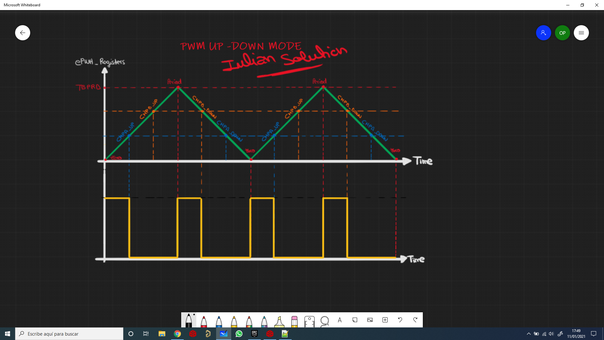
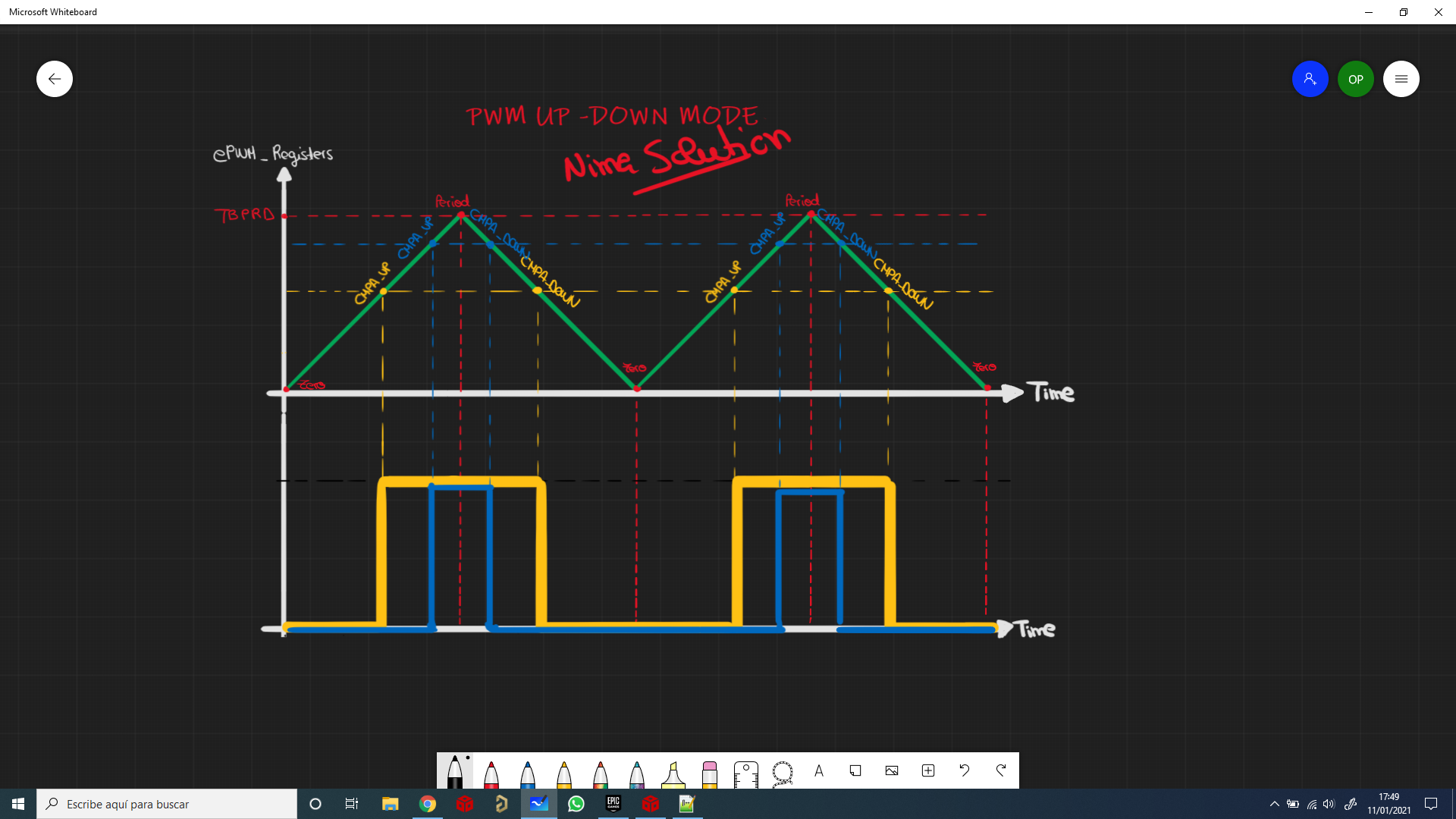
    2 - OK. Understood. I´ve changed my EPWM config to use only CMPA_UP and CMPA_DOWN. In my solution I used CMPA and CMPB UP/DOWN. In this way of configuring the EPWM, the frequency of the EPWM is half and the duty is controlled directly by CMPA, right? (See screenshoot)

    3 - "If you use the ZERO/PRD event to change the EPWM output (set/clear) you get the jump."--> So my EPWM OUTPUT is only refreshed on CMPA_UP (set) and CMPA_DOWN (clear).

    I will try this configuration tomorrow when I get to the university and give you an answer.

      Iulian.

  • Thank you. I tested the code below with 100% correct results:

    void initEPWMFIX(uint32_t base)
    {
        //
        // Set-up TBCLK
        //
        EPWM_setTimeBasePeriod(base, EPWM_TIMER_TBPRD);
        EPWM_setPhaseShift(base, 0U);
        EPWM_setTimeBaseCounter(base, 0U);
    
        //
        // Set Compare values
        //
        EPWM_setCounterCompareValue(base,
                                    EPWM_COUNTER_COMPARE_A,
                                    EPWM_TIMER_TBPRD/2);
        EPWM_setCounterCompareValue(base,
                                    EPWM_COUNTER_COMPARE_B,
                                    EPWM_TIMER_TBPRD/4);
    
        //
        // Set up counter mode
        //
        EPWM_setTimeBaseCounterMode(base, EPWM_COUNTER_MODE_UP_DOWN);
        EPWM_disablePhaseShiftLoad(base);
        EPWM_setClockPrescaler(base,
                               EPWM_CLOCK_DIVIDER_1,
                               EPWM_HSCLOCK_DIVIDER_1);
    
        //
        // Set up shadowing
        //
        EPWM_setCounterCompareShadowLoadMode(base,
                                             EPWM_COUNTER_COMPARE_A,
                                             EPWM_COMP_LOAD_ON_CNTR_ZERO);
        EPWM_setCounterCompareShadowLoadMode(base,
                                             EPWM_COUNTER_COMPARE_B,
                                             EPWM_COMP_LOAD_ON_CNTR_ZERO);
    
        //
        // Set actions
        //
        EPWM_setActionQualifierAction(base,
                                      EPWM_AQ_OUTPUT_A,
                                      EPWM_AQ_OUTPUT_HIGH,
                                      EPWM_AQ_OUTPUT_ON_TIMEBASE_UP_CMPA);
        EPWM_setActionQualifierAction(base,
                                      EPWM_AQ_OUTPUT_B,
                                      EPWM_AQ_OUTPUT_HIGH,
                                      EPWM_AQ_OUTPUT_ON_TIMEBASE_UP_CMPB);
        EPWM_setActionQualifierAction(base,
                                      EPWM_AQ_OUTPUT_A,
                                      EPWM_AQ_OUTPUT_LOW,
                                      EPWM_AQ_OUTPUT_ON_TIMEBASE_DOWN_CMPA);
        EPWM_setActionQualifierAction(base,
                                      EPWM_AQ_OUTPUT_B,
                                      EPWM_AQ_OUTPUT_LOW,
                                      EPWM_AQ_OUTPUT_ON_TIMEBASE_DOWN_CMPB);
    
    
        HRPWM_setMEPEdgeSelect(base, HRPWM_CHANNEL_A, HRPWM_MEP_CTRL_RISING_AND_FALLING_EDGE);
        HRPWM_setMEPControlMode(base, HRPWM_CHANNEL_A, HRPWM_MEP_PHASE_CTRL);
        HRPWM_setCounterCompareShadowLoadEvent(base, HRPWM_CHANNEL_A, HRPWM_LOAD_ON_CNTR_ZERO_PERIOD);
    
        HRPWM_setMEPEdgeSelect(base, HRPWM_CHANNEL_B, HRPWM_MEP_CTRL_RISING_AND_FALLING_EDGE);
        HRPWM_setMEPControlMode(base, HRPWM_CHANNEL_B, HRPWM_MEP_PHASE_CTRL);
        HRPWM_setCounterCompareShadowLoadEvent(base, HRPWM_CHANNEL_B, HRPWM_LOAD_ON_CNTR_ZERO_PERIOD);
    
        HRPWM_enableAutoConversion(base);
    
        HRPWM_enablePhaseShiftLoad(base);
    
        //
        // Interrupt where we will change the Compare Values
        // Select INT on Time base counter zero event,
        // Enable INT, generate INT on 1rd event
        //
        EPWM_setInterruptSource(base, EPWM_INT_TBCTR_ZERO);
        EPWM_enableInterrupt(base);
        EPWM_setInterruptEventCount(base, 1U);
    }


    Nima

  • Thank you a lot Nima. These points of your answer were the key!!

    "2. Use only CMPAU/CMPAD for your EPWM output changes. SET on CMPAU, Clear on CMPAD.

    If you use the ZERO/PRD event to change the EPWM output (set/clear) you get the jump."

    Now the phase shift works perfect!!!

    Thank you for your time and dedication.

    Iulian.

  • Glad that worked! That was a tough one.