This thread has been locked.

If you have a related question, please click the "Ask a related question" button in the top right corner. The newly created question will be automatically linked to this question.

CCS/TMS320F28379D: Positive going zero cross detection using zero cross detection logic

Part Number: TMS320F28379D


Tool/software: Code Composer Studio

Hi,


I am trying to toggle the GPIO output only at the positive-going zero-cross. "Zero cross detection logic Hardware" of the TMS320F28379D (See the attached figure for the reference) gives an interrupt for both positive as well as negative-going zero crosses.

In order to detect the positive crossing, I have written the following logic inside the adca_ppb_isr function. However, GPIO is getting toggled at both positive and sometimes at negative zero crossings.  

//***********************************************************************************************

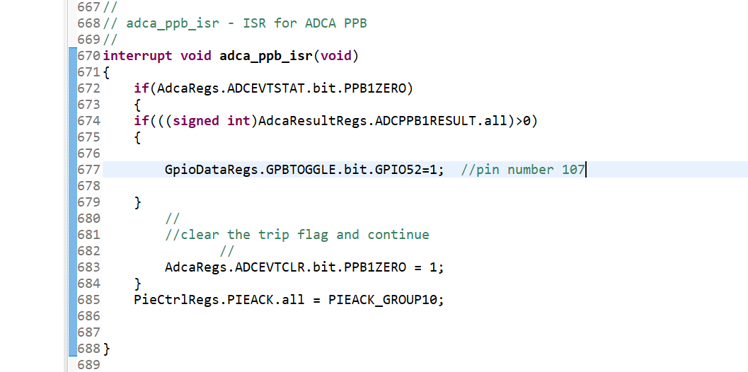
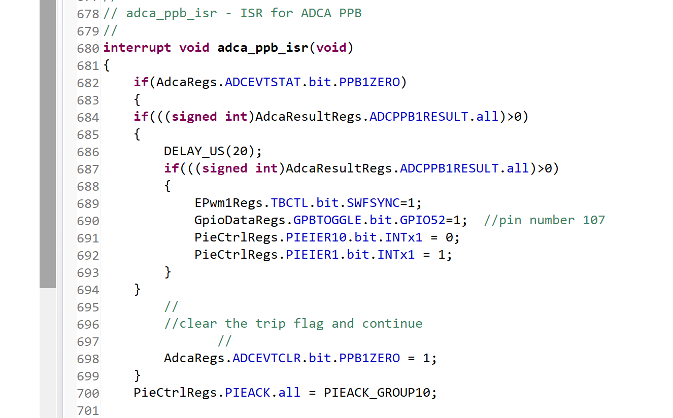
interrupt void adca_ppb_isr(void)
{
if(AdcaRegs.ADCEVTSTAT.bit.PPB1ZERO)
{
if(((signed int)AdcaResultRegs.ADCPPB1RESULT.all)>0)
{
GpioDataRegs.GPBTOGGLE.bit.GPIO52=1; //pin number 107
}
//
//clear the trip flag and continue
//
AdcaRegs.ADCEVTCLR.bit.PPB1ZERO = 1;
}
PieCtrlRegs.PIEACK.all = PIEACK_GROUP10;


}

//***********************************************************************************************

Can anyone help me to implement the only positive zero crossing using this "Zero cross detection logic Hardware".  Thanks in advance.

Regards

Manikanta P

  • Manikanta,

    Neat idea. Have you evaluated what the result value in "ADCPPB1RESULT" is when your "if" statement is evaluated? That might help shed some light on if you need a bit of a pass band on this result.

    Are you sure that the if statement is processing the same ADC reading which tripped the ISR?(i'm not an ADC expert, so if you need help here i'll have to point you to someone else.

    Regards,
    Cody 

  • Hi Cody,

    Thanks for the reply. I did compare the values just before the interrupt and inside the interrupt. That's how I came up with this logic. However, It was not working as expected. So, I modified the code as below.

    Here I am comparing the ADC values after a sample period. It is working fine. But the problem is that GPIO is toggling after 20us at every positive-going zero cross. I was wondering is there any better implementation compared to the above method so that there wont be any delay. Thanks for your time.

  • 20us seems like a long time. Do you have any other interrupts enabled? 

    Can you toggle an GPIO right at the beginning of the ISR to see if it is delayed?

    Please note I would not recommend adding a delay in any ISR code.


    Regards,
    Cody 

  • Hi cody,

    Thanks for your response. I have checked whether the signal get delayed by adding another GPIO right before and right after the delay statement. It's perfectly working fine. Also My requirement is that I had to detect positive zero crossing only once throughout the operation. So once its detected I have disabled this interrupt. During this interrupt, there are no other interrupts enabled. So Do you think implementing this way is fine? I still want to get rid of that delay 20us. Could you suggest any better way to do this? Thanks for your time. 

    Regards

    Manikanta P

  • Manikanta,

    if you are only running the ISR once or twice its probably fine, my comment was assuming that this ISR would run frequently in your code. If this is more of a "initialization  ISR" then isn't used, then this probably doesn't hurt your execution time too much and would be OK.

    Regards,
    Cody 

  • Great, thank you so much.

    Regards

    Manikanta P