This thread has been locked.

If you have a related question, please click the "Ask a related question" button in the top right corner. The newly created question will be automatically linked to this question.

TMS320F280049C: Use DCCAP capture PWM period issue

Part Number: TMS320F280049C

Hi Nima,

Issue: DCCAP cannot capture right PWM period.

Background:
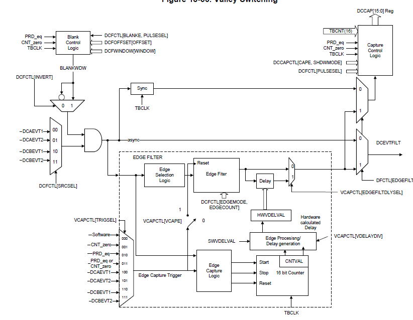
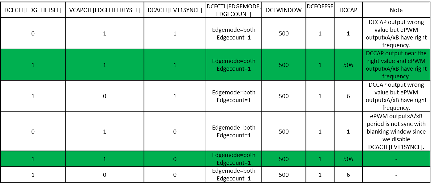
(1) When I configure the DCFCTL[EDGEFILT]=1, the DCCAP can capture right period value. However, PWM can sync with DCEVTFILT correctly. 

(2) When I configure the DCFCTL[EDGEFILT]=0, the DCCAP can capture right period value. PWM can sync with DCEVTFILT correctly. 

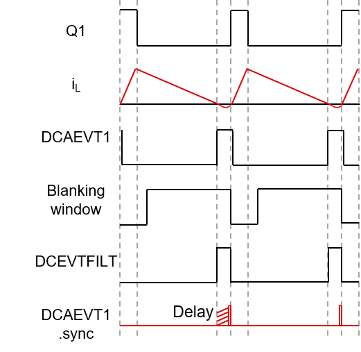
(3) I configure the CMPSS, XBAR, ePWM DC submodule and they should generate waveform as shown below.
  • Background supplement:

    I set period of sync signal (DCAEVT1.sync) 200kHz

    (1) DCFCTL[EDGEFILT]=1, ePWM.DCCAP as shown in expression is 497~500(correct).

    (2) DCFCTL[EDGEFILT]=0, ePWM.DCCAP as shown in expression is 1(wrong).

  • Yes unfortunately the blanking window doesnt blank immediately after CTR=ZERO. Blanking window takes 3 cycles to start blanking. We are aware of this and will add it to the ERATTA. This is already mentioned in the F2837xD device eratta. Will be added to this device as well.

    Nima

  • Hi Nima,

    There is another issue.

    (1) TB sub-module sync signal, which is generate by DCAEVT1.sync, start TBCTR sync by only rising edge? Or both rising edge and falling edge can trigger TB sync?

    (2) DC capture logic block (DCCAP) only capture rising edge event or both edge event (to copy TBCTR's value into DCCAP)?

    Thanks!

    -Minghan

  • Question supplement:

    (3) Why (DCAEVT1 ORed Blanking window) signal flow though edge filter is not influence by blanking window? DCCAP can capture right period in this situation in my test.

  • 3) Becuase the signals are not edge based and they are LEVEL based. So when you use the EDGE filter, you make it edge based and it works.

    2, 1) I believe they are level based. The Gate to enable the synchronization/ the gate to capture the DCCAP value are both level based.

    Nima

  • Thank you very much!

     In EDGE filter, the edge transfer to level? I mean: the edge comes into the edge filter then the output of edge filter becomes high from low?

    But what's the output of edge filter when the second edge comes into the edge filter(if I set DCFCTL[EDGECOUNT]=001, the edge filter process ever edge)?

    Many Thanks!

  • Another question:

    (1) From my test, why only DCFCTL[EDGEFILTSEL]=1 AND VCAPCTL[EDGEFILTDLYSEL]=1 can capture nearly right value?

    Why VCAPCTL[EDGEFILTDLYSEL] must set?

    (2) How to explain to customer about the 6 clocks error? Because the right value should be 500 but the capture value is 506.

    Thank you very very much!

    -Minghan

  • Back ground supplement:

    For testing purpose, I disable the delay block (initialize by VCAPCTL[EDGEFILTDLYSEL]=1) so that it will not add any delay to the edge selected by edge filter block. (VCAPCTL[VDELAYDIV]=000, HWVDELVAL = SWVDELVA=0 as shown in TRM).

  • Minghan Dong said:
    How to explain to customer about the 6 clocks error? Because the right value should be 500 but the capture value is 506.

    Minghan,

    Actually seems like you have found a mode that is somewhat a workaround for our BLANKING WINDOW eratta.

    EDGEFILTDLYSEL = 1 seems to allow the blanking window issue to not be inserted in the logic. I'm not sure why this is actually working.

    For you 506 (the extra 6), there actually is an explanation. So your signal goes through, possibly the GPIO input, INPUT XBAR, EPWM XBAR, then finally the delay block. The XBARs each add a 1-2 cycle delay. The extra 6 is caused by the delay in the signal chain.

    Nima

  • Minghan Dong said:
     In EDGE filter, the edge transfer to level? I mean: the edge comes into the edge filter then the output of edge filter becomes high from low?

    Yes, once the EDGECOUNT number of edges arrive, the signal goes high.

    When the value matches the EDGECOUNT a TBCLK wide pulse is generated which can then be output on the DCEVTFILT signal. 

    VCAPCTL[VCAPE] enabled and VCAPCTL[TRIGSEL] will determine what resets the EDGECOUNT counter.

    Nima