This thread has been locked.

If you have a related question, please click the "Ask a related question" button in the top right corner. The newly created question will be automatically linked to this question.

TMS320F28377S: Code generation error

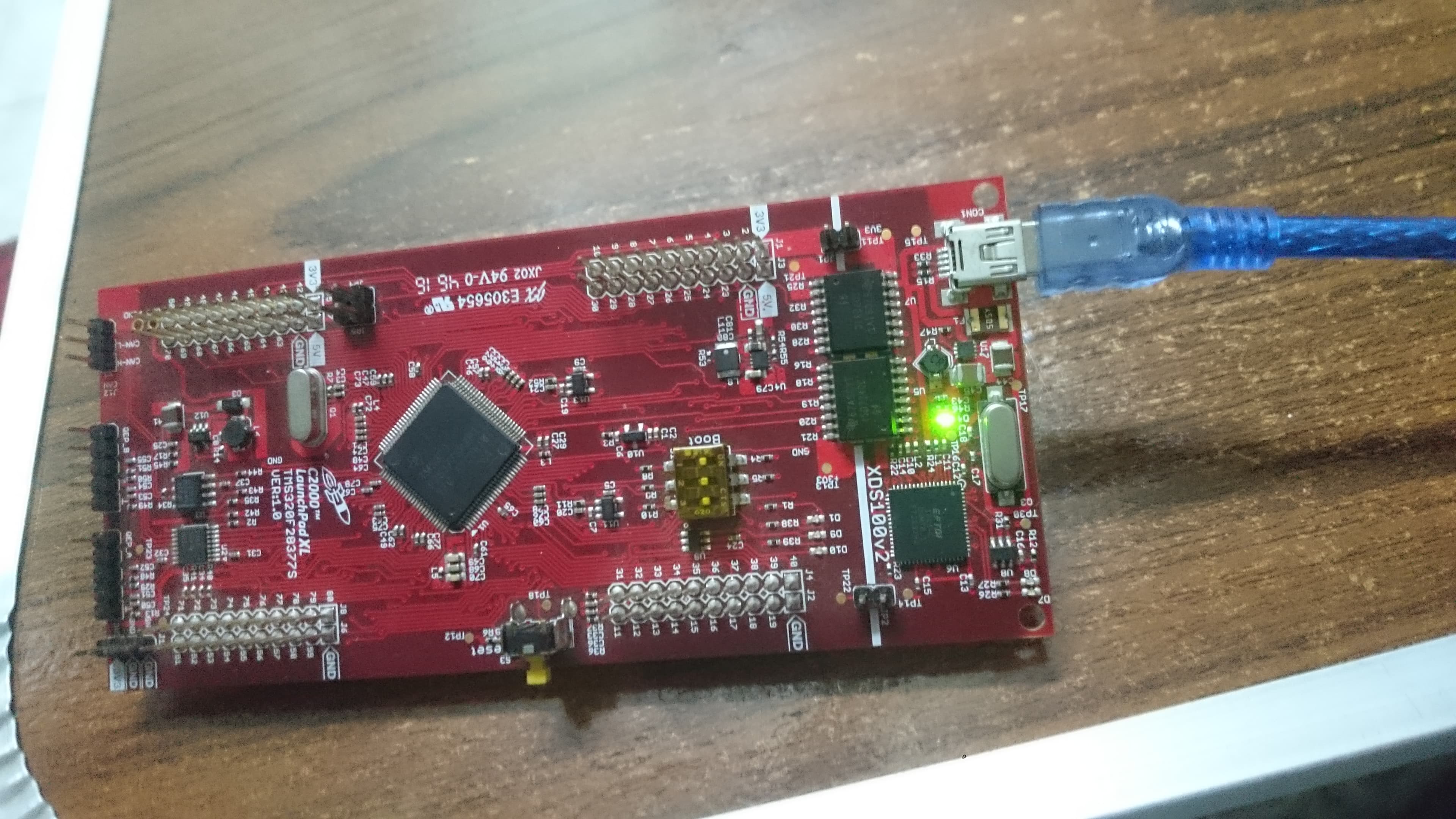
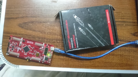
Part Number: TMS320F28377S

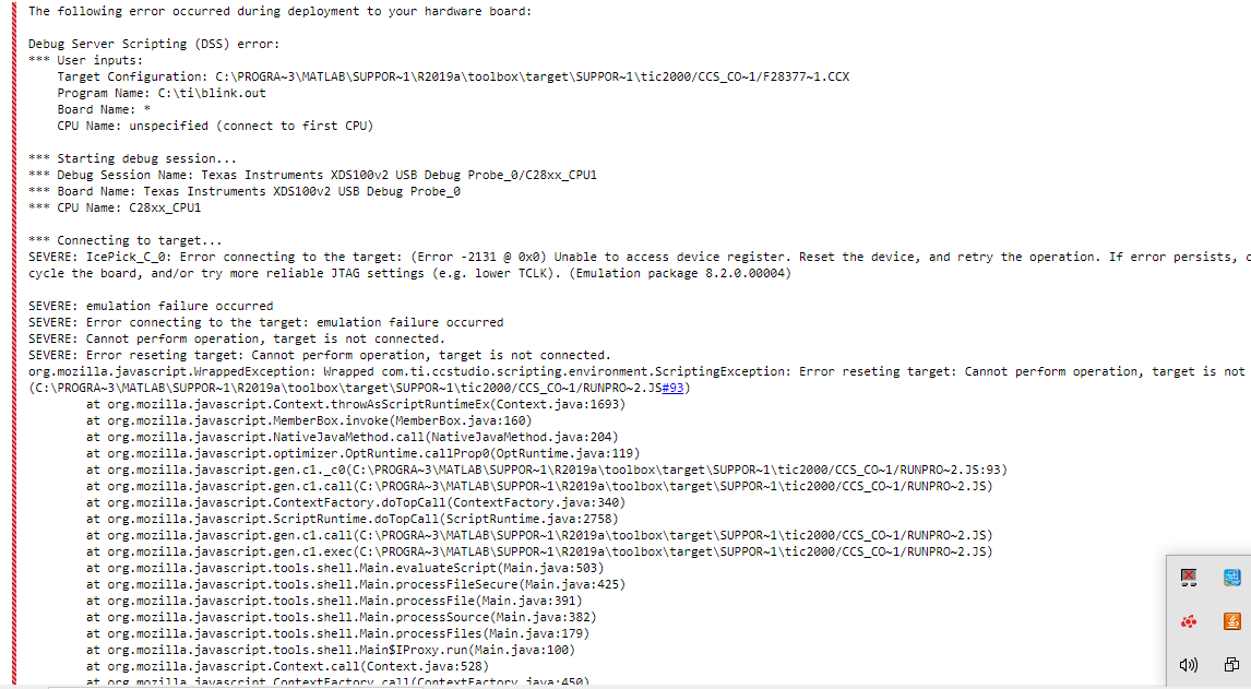
I have an error when i run a simple code to my MCU.

The device is recognized in device manager.

I am using CCS version 9.1.0 and matlab 2019a

I

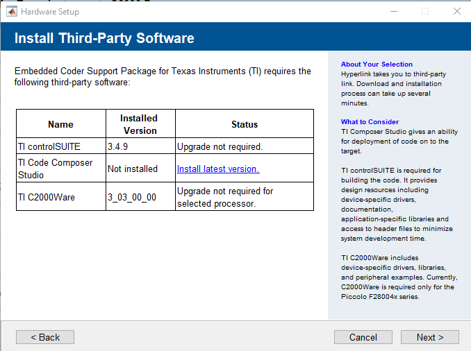
I installed the Embedded coder package from the addon and all the third party products. but when I go to manage application and choose the embedded coder it verifies all the products but the CSS.

then it asks to validate its location and it is validated successfully ( idk if the problem is from ccs)

  • Khaled,

    I may ask the MW team to comment on the 3rd party installation message, I'm not sure if this is indicative of Simulink not finding the CCS install dir that would cause this issue, or something we can ignore.  Even though CCS v10 is the latest, given you are using the 2019a build I think CCS v9 would be OK.

    If you open CCSv9 that you have installed on its own are you able to configure the target and connect normally?  We will need to isolate if this is a connection problem vs a Simulink issue. 

    Can you also comment if you are using one of our eval kits, like the controlCARD or is this a custom PCB?

    Best,

    Matthew

  • In CCS i cannot configure the device so i believe its a connection problem. I am not using a custom PCB 

    I noticed that when i connect the device to the PC a green led (D4) is on and when i press reset nothing happen it remains on. I saw some videos when the device is connected the blue and red leds are on not the green. I would like to know what does the green led mean. Also iam not using the usb cable that came with the kit but i am sure my usb is working. 

  • Khaled,
    Thanks for posting the picture and the information.  This is the LAUNCHXL-F28377S, and the green light means that it is getting power from the USB.

    The issue is that the MCU is not getting power, you need place a jumper across JP1(3.3V) and place a jumper across JP2(GND)(these are the jumpers that straddle the white line across the PCB).  The schematic is here . 

    After you do this the MCU should be powered and then try the connection(first with CCS, then Simulink if that works).

    Depending on the state of the flash in the device you may see the red/blue toggle, this is the default program from TI.  Even if these don't flash it shouldn't prevent you from connecting.

     If you still can't connect I'd remove the yellow film from the "boot" switch and place the device in Wait Boot mode(See page 4 of the above schematic).

    Best,

    Matthew