This thread has been locked.

If you have a related question, please click the "Ask a related question" button in the top right corner. The newly created question will be automatically linked to this question.

CCS/TMDSHVMTRINSPIN: Inline current sensing and spin the motor using TMDSHVMTRINSPIN(HV-KIT)

Part Number: TMDSHVMTRINSPIN
Other Parts Discussed in Thread: TMDSADAP180TO100, TMS320F280049C, , C2000WARE, AMC1300

Tool/software: Code Composer Studio

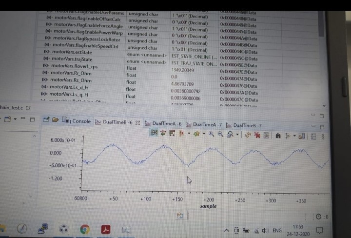
We could control motor with  TMDSHVMTRINSPIN development kit, TMS320F280049C control card  and TMDSADAP180TO100, by loading the example projects presented in below path "C:\ti\c2000\C2000Ware_MotorControl_SDK_3_00_01_00\solutions\tmdshvmtrinspin\f28004x\ccs\sensorless_foc ". Now we are going to run the motor by changing the hardware as shown in below image( modified hardware) we sense the current at inline resistors.

1.  We disconnected  R14,R16,R17,R33,R34,R41 on HV-kit  and we connect like below image (modified hardware), Is this HW good for testing?

2. I understand from Steve Lim‘s answer no code change is needed. (Refer to 28/Sep post by Steve Lim: https://e2e.ti.com/support/microcontrollers/c2000/f/171/p/940417/3487721#3487721).

"Both currents are same motor winding current at zero vector. So there is nothing you have to change the code if you keep same current sensing polarity".

We have a doubt on Keeping current sensing polarity. Can you please help us understand how to do that?

3. With the new HW changes, shall I start from Lab1 again?

Thank you

  • 1. You might take a look at the reference design at the following link (https://www.ti.com/tool/TIDA-010025

    et correct parameters based on the hardware board in user.h, and make sure that the sign of the current coefficient in HAL_readAdcData() in hal.h matches the current sensing circuit.

    #define USER_IQ_FULL_SCALE_VOLTAGE_V           (xx)

    #define USER_VOLTAGE_FILTER_POLE_Hz               (xx)

    #define USER_ADC_FULL_SCALE_VOLTAGE_V       (xx)

    #define USER_IQ_FULL_SCALE_CURRENT_A           (xx)

    #define USER_ADC_FULL_SCALE_CURRENT_A       (xx)


    static inline void HAL_readAdcData(HAL_Handle handle,HAL_AdcData_t *pAdcData)

    {

       _iq current_sf = HAL_getCurrentScaleFactor(handle);

    }

     3. Yes, it's better to do this to verify the sensing signals and settings.

  •  thanks for the reply, 

  • All of the changes I have mentioned above. Please check if the phase voltages are sensed correctly, and try to run the lab03 and lab04 as the lab guide to verify the current and voltage sensing first before you run the subsequent labs.

  • I haven’t heard from you for a week, so I’m assuming you were able to resolve your issue. Please let me know if you have any questions. We would like to close this thread if no any further questions. Thanks.

  • Hi, Thanks for the reply,

    We followed the reference guide provided by you ((https://www.ti.com/tool/TIDA-010025) and we changed the hardware (20mohms inline and total gain of AMC1300 plus Opamp is approx. 8) as shown in that user guide. We tested the modified Current sense Hardware by applying 3A current from a DC-source and we can see clear waveforms at the output of Differential to single ended OpAmp of phases U, V & W.Then we connected to motor, flash the lab05, we get the below values.

    motorVars.VdcBus_V = 329v

    motorVars.Rs_Ohm = 461

    motorVars.Ls_d_H = 0.009

    motorVars.Ls_q_H =0.0078

    However when we try to run, fuse is failing often. We can see Motor trying very hard to rotate.

    Also tried changing the sign of the current coefficient in HAL_readAdcData() in hal.h, we face the same problem( fuse damage). When we test by disconnecting the motor, there is no damage of fuse. To note, we could run the motor using Low side Current sense Resistors.

    These are the values I set in user.h file

    #define USER_NOMINAL_DC_BUS_VOLTAGE_V         ((float32_t)(400.0))

    #define USER_ADC_FULL_SCALE_VOLTAGE_V         ((float32_t)(409.6))

    #define USER_ADC_FULL_SCALE_CURRENT_A         ((float32_t)(20.00))

    #define USER_VOLTAGE_FILTER_POLE_Hz           ((float32_t)(372.5))

    #define   IA_OFFSET_A   (9.97279739)          

    #define   IB_OFFSET_A   (9.95302963)          

    #define   IC_OFFSET_A   (9.89870834)  

    The below is my motor name plate:

    thank you

  • What capacitance are the two capacitors in the current sensing circuit?

    Did you try to run lab03 and lab04 to verify the current sensing since you are not using the TI EVM kit? Please show some current and voltage sensing waveforms in lab03 and lab04 if you still have any issues to run the motor.

  • Hi, Thanks for quick answers. Our HW is shown in below image:

    Our HW has 10nf capacitor at input side of AMC1300 and we use 2nf capacitor at the output of OPAMP. We run the lab03, and lab04 we get the below result, but we face an issue with fuse failing.

    Below are from Lab03:


    Below are the lab04 waveforms, we didn’t get any signals in 2 graphs


    thank you

  • The lab03 should spin the motor well without loading or with a light load if you set the below parameters correctly according to the spec. of your motor.  Because the lab03 doesn't use any phase current and voltage feedback signals, just need to use the dc bus voltage sensing signal. 

    #define USER_MOTOR_FREQ_LOW                                (10.0)                        // Hz - suggested to set to 10% of rated motor frequency

    #define USER_MOTOR_FREQ_HIGH                                     (100.0)                        // Hz - suggested to set to 100% of rated motor frequency

    #define USER_MOTOR_FREQ_MAX                                (120.0)                        // Hz - suggested to set to 120% of rated motor frequency

    #define USER_MOTOR_VOLT_MIN                                (3.0)                        // Volt - suggested to set to 15% of rated motor voltage

    #define USER_MOTOR_VOLT_MAX                                (18.0)                        // Volt - suggested to set to 100% of rated motor voltage

     If the motor can't run smoothly in lab03 after you tuned the above parameters, you have to check if the inverter is workable.

    Both lab03 and lab04 don't use the phase voltage sensing signals and don't implement the FAST estimator. So you can add a big filter capacitor to the current sensing circuit. You might remove the 10nF and 330pF capacitors in the current sensing if you want to use the FAST estimator in the subsequent labs. You must make sure that the lab04 can spin the motor well and the sensing current signals are right for the motor drive. Please refer to lab03 and lab04 guide to use the datalog and PWMDAC to verify the sensing current signals and ADC configuration in the project.

    Since the issue should be from the current sensing circuit you changed, you have to fix it as we mentioned above by yourself, we would like to close the thread first. Please let's know if you have any further questions.

  • Hi thanks for the reply

    We update the user.h file with the new parameters said by you, we sucessfully spin my motor with lab03, we remove the 10nF and 330pF and we put the 100nF at the current sensing circuit. after placing 100nF we flash the lab04, but when we set motorVars.flagRunIdentAndOnLine = 1 in watch window, my fuse was burned.

    we put the below parameters in user.h 

    #define USER_MOTOR_FREQ_MAX_HZ (60.0

    #define USER_MOTOR_FREQ_LOW_HZ (5.0)

    #define USER_MOTOR_FREQ_HIGH_HZ (50.0) 
    #define USER_MOTOR_VOLT_MIN_V (45.0) 
    #define USER_MOTOR_VOLT_MAX_V (300.0)

    #define USER_ADC_FULL_SCALE_CURRENT_A    ((float32_t)(19.89))

    #define USER_ADC_FULL_SCALE_VOLTAGE_V         ((float32_t)(409.6))

    #define USER_VOLTAGE_FILTER_POLE_Hz           ((float32_t)(372.5))

    My hardware: 

    Lab03 result waveforms :

    thank you

  • 1.Please don't use a 100nF capacitor, use a small one like 2.2 or 3.3nF.

    2. It seems like the sensing current is not correct in lab03. Please try to use datalog and PWMDAC to monitor the sensing current and voltage in lab03. Don't run the subsequent labs before you can get the same current/voltage signal sampling waveforms as the example in the lab guide. And the waveforms from datalog or PWMDAC should be very similar to the waveform capture by the oscilloscope with a current probe.

  • Hi, thanks for your support

    In my new hardware we measures the both -ve and +ve feedback currents at inline resistors, i referred spruhj1h.pdf  for current feed back, in 5.2.2.1 chapter, there is code changes presented for either +ve feedback or -feedback.

    1. is it there any chances to failure of  fuse because of this multiple polarity of feedback current? because every time after lab03 my fuse was burned

    thank you

  • Yes, the motor will be overcurrent and the fuse will be buried if the sensing current is not correct when you run lab04 or the successive labs. Please check if the sensing current is correct using the lab03, don't run the successive labs after lab03 if you can't get the feedback current signals with datalog or PWMDAC as lab guide.

  • Hi thanks for your support, in lab03 i got current waves as shown in user guide, my motor spin successfully.

    1. Can I use the same motor parameters (which I used For lab03, 04)For further labs also?

    Thank you

  • Lab03 and lab04 don't use any motor parameters. You should use lab05 to identify the motor parameters for the successive labs, Of course, you can the motor parameters identified or run well on other kits.

  • Thank you sir for your support