This thread has been locked.

If you have a related question, please click the "Ask a related question" button in the top right corner. The newly created question will be automatically linked to this question.

TMS320F280041C: Sensorless PMSM not reaching speed with Instaspin-FOC and FAST

Part Number: TMS320F280041C


Running CC version 9.3 on a custom motor control board with an TMS320F280041C onboard. Compiler TI v18.12.5.LTS, C200Ware version 2.00.00.03, Motor Control SDK 2.00.00.00.
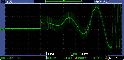
We are trying to run a PMSM in sensorless mode using  Lab is07 (described in the InstaSPIN Projects and Labs User's Guide Vers 1.00.00.00) with the FAST algorithm and force angle enabled, with 1 Hz switchover to FAST. The motor's max speed is 370 Hz but when commanding greater than 200 Hz, the motor trips. From the user guide, chapter 14, and previous posts like:

https://e2e.ti.com/support/microcontrollers/c2000/f/171/p/502880/1821864#1821864


we thought we need to align the rotor first by doing an offline Rs recal. Enabling the Rs recal flag: motorVars.flagEnableRsRecalc in the initialization portion of code before running is07 does not work. In fact, the motor buzzes with the current oscillating and increasing exponentially until the motor current trips.

What should be the correct code to align the rotor at startup, and can the is07 code run afterwards to spin the motor up to, or close to its max speed?

We also noticed that the speed oscillates when a new speed command is given. It eventually settles but we're aware we need to tune the velocity loop.

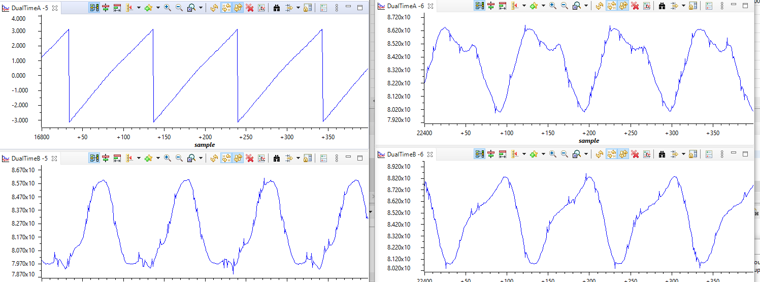
When running the is04 lab we noticed that the Angle generator output was 0 to 2*pi. When running the is07 lab we noticed that the FAST angle output was -pi to +pi. Could this be causing a phase offset of pi, preventing the motor from reaching high speeds? If yes, is there a way to adjust?

We also noticed that the user.h parameters don't exactly match those in the InstaSPIN-FOC User's Guide SPRUHJ1H (June 2019) making debug harder.
Thanks in advance for your help.

  • Are you using the TI EVM kit or your own board? Did you try to run the lab05 to identify the motor parameters and use the identified parameters for running the lan07?

  • Thanks for your reply.

    Yes, we've run the motor ID code and used those parameters and we are using our own board. Upon further testing we see that is07 does seem to perform an alignment at initialization to a known zero rotor position we've marked. Besides not being able to reach speed, we've noticed that at low speeds the motor oscillates in speed and doesn't quite settle. We think both cases indicate that the angle output of the FAST algorithm is not correct. Could it be that at higher speeds, the angle phase "slips" and needs to be corrected by adding some phase table vs speed? Or are some of the parameters fed into the FAST not correct? In the past, with other algorithms, we've determined that the motor inductance value has a big effect on the estimated angle.

  • Force angle (open loop control) is used for the startup and low speed, so there could be a little bit of oscillating during startup at the first rotation., especially the motor with a heavy load.

    Did you use lab03 and lab04 to verify the current and voltage sensing since you are working on your own board? And could you please post some current waveforms to show the issue that could help us to understand your questions? If possible, do you have a chance to run the motor with TI EVM kits and see what happens?

    You don't need to add any angle compensation according to the speed, the FAST estimator has had this function already. You just need to make sure that the hardware board is good enough for motor drive and set the correct parameters in user.h based on the hardware and motor.

  • We have used an EVM kit but on a different motor. Below is graph of Id_ref ( Idq_ref_A.value[0] ), and estimated angle. This is a PM motor, so seems strange that Id_ref isn't zero, but a -6A - +4A sine.  As far as I know, it's not running Rs online recalibration or field weakening.

    In the graph, the motor is commanded to increase speed from 75 Hz to 200 Hz, then it stalls close to 200 Hz. Max motor speed is 370 Hz.

  • Do you mean the motor speed is electrical frequency set by the variable " motorVars.speedRef_Hz"?

    Can you check the "userParams.maxVsMag_V" and "motorVars.Vs_V" in the expression watch window? To see if the value of both variables is very close.  If yes, please increase the dc bus voltage of the inverter to see what happens.

  • Hi. Yes the electrical frequency in Hz. It's an 8 pole motor, 2900 RPM - so Max speed around 390 Hz. Using lab07 motor starts up about half the time, when it does, current at 75 Hz is about 2 A. When increasing speed to 200 Hz, current increases to 20A until there is a motor sudden stall. We are applying 48V and it's a 48V motor so it should achieve velocity higher than 200 Hz. When we use lab04 and Iq = 18A the motor spins no problem past 300 Hz. This is probably because we are applying a large current.

    For the speed closed loop lab07, is there an initial rotor alignment built in? We think the big increase in current at higher speeds is due to the estimated angle misalignment getting worse at higher speeds.

  • Did you try to identify and run the motor using the TI EVM kit, and have a comparison with the test result on your own board?

    And did you have any waveforms of the motor phase current captured by the oscilloscope with a current probe?

  • We haven't tried the motor ID using a TI EVM kit, just our custom board. Could this potentially change some motor parameters? Is the correct sequence to perform the motor ID on a TI EVM kit and then copy the parameters to the user.h file when using a custom board?

    Below are startup currents for the 3 phases running  lab07 with forced angle enabled, run 3 different times as we only have one current probe. From this we can see that there is no initial rotor lock or alignment, and when we try to enable it as described in an earlier post, the motor buzzes and current just oscillates, increasing in magnitude until it trips. Is there another way to implement a rotor alignment without using the offline Rs Recalibration enable or is there something in the lab07 code that doesn't allow this method of rotor alignment?

    Below are CC graphs of the FAST estimated angle and the 3 current phases taken with the motor spinning at 75 Hz (about 560 RPM) running lab07. When the speed is increased to 200 Hz (1500 RPM), the currents increase 10x and the motor stalls.

    The latest user.h file attached0841.user.h

  • Do you have any chance to identify and run the motor on the TI EVM kit? It seems like current waveforms are not good. Can you run the motor at a low speed and capture the waveforms as above?

    InstaSPIN-FOC doesn't use the rotor lock and initial position detect for a startup, just use the force angle.

  • We will set up the motor with our EVM kit and let you know results.  We understand there is no initial position detect, but are surprised to learn that there is no rotor lock for sensorless applications. In the InstaSPIN-FOC User's Guide SPRUHJ1H in Chapter 14 they mention ways of managing full load at startup, and the technique described is to do a rotor alignment (we used to call it rotor lock, but same thing) at startup by applying a DC current. Following this technique has not worked for us using different lock currents and delays. Is there an error in the manual? With InstaSPIN-FOC there is no different way of starting up a motor under full load?

  • You can still use the Rs recalibration to force the rotor to an initial position for a startup in all of the instaspin labs in motor control SDK. Or apply a DC current on d-axis as you mentioned above to force the rotor to zero angle position and then set the estimation angle to zero by calling EST_setAngle_rad().  

  • As mentioned previously, using the Rs recalibration to force the motor to an initial position hasn't worked using the function in the InstaSPIN user guide. The current rises exponentially. We have applied a DC current on the q-axis for 3 seconds while setting the rotor to zero angle as you described, but we don't seem to see the q axis current command change to the DC value commanded for the time commanded. Could you provide the function that we could  use to implement this?

  • Set a torque current value to Idq_offset_A.value[1] directly.

  • We had to disable the estimator before performing the startup, then enabling. Initial rotor alignment seems to be working as expected.