This thread has been locked.

If you have a related question, please click the "Ask a related question" button in the top right corner. The newly created question will be automatically linked to this question.

CCS/TMS320F28379D: CCS/F28379D

Part Number: TMS320F28379D

Tool/software: Code Composer Studio

Hi,

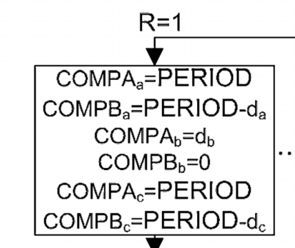
I am trying to implement a PWM method called AZSPWM1 (Active Zero State PWM). In the implementation of this PWM method, I need to assign different values to CMPA and CMPB registers of EPWM in each sector. The required task is shown in the picture attached. I am doing that task in DSP as follows:

    if (sector == 1)

    {

        EPwm7Regs.CMPA.bit.CMPA = INV_PWM_TBPRD;

        EPwm7Regs.CMPB.bit.CMPB = INV_PWM_TBPRD - usCmpValA;

        EPwm8Regs.CMPA.bit.CMPA = usCmpValF AZS PWM with DCDC - Generalized Scalar.rarB;

        EPwm8Regs.CMPB.bit.CMPB = 0;

        EPwm9Regs.CMPA.bit.CMPA = INV_PWM_TBPRD;

        EPwm9Regs.CMPB.bit.CMPB = INV_PWM_TBPRD - usCmpValC;

    }

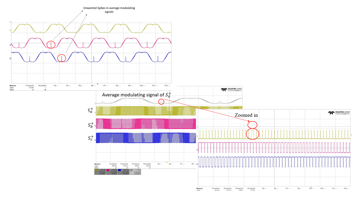
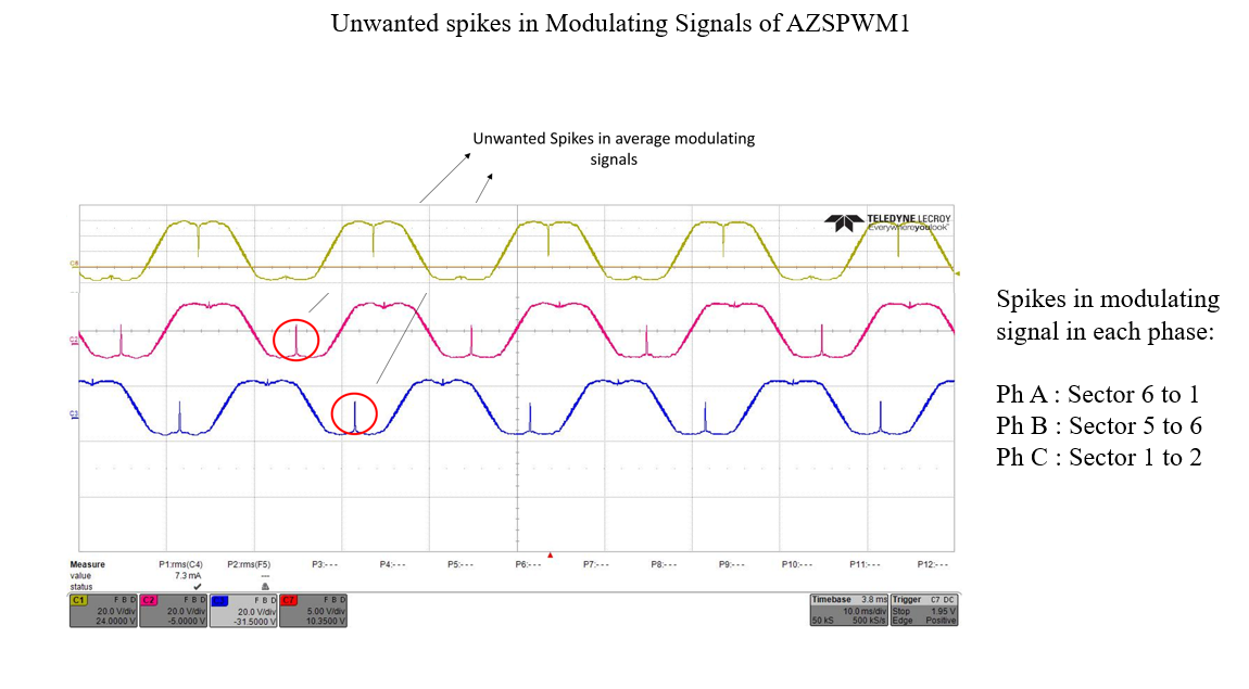
But my resultant PWM signals are not as expected. Can  you please guide me what am I missing?  I am also attaching my DSP code for reference.

  • You are setting CMPA, CMPB to PRD or ZER?

  • My PWM setting is this

  • It did not go through. I am asking if ever the value written to CMPA, CMPB is 0 or your PRD value?

    Nima

  • The values in CMPA and CMPB are varying duty cycles, ranging from 0 to 1 (PRD) value.

    I am pasting the PWM CMPA and CMPB assignments and PMW settings in the text below.

    ======================== CMPA and CMPB values in each Sector ===================================

    if (sector == 1)
        {
    
            EPwm7Regs.CMPA.bit.CMPA = INV_PWM_TBPRD;
            EPwm7Regs.CMPB.bit.CMPB = INV_PWM_TBPRD - usCmpValA;
            EPwm8Regs.CMPA.bit.CMPA = usCmpValB;
            EPwm8Regs.CMPB.bit.CMPB = 0;
            EPwm9Regs.CMPA.bit.CMPA = INV_PWM_TBPRD;
            EPwm9Regs.CMPB.bit.CMPB = INV_PWM_TBPRD - usCmpValC;
    
        }
        else if (sector == 2)
        {
    
            EPwm7Regs.CMPA.bit.CMPA = INV_PWM_TBPRD;
            EPwm7Regs.CMPB.bit.CMPB = INV_PWM_TBPRD - usCmpValA;
            EPwm8Regs.CMPA.bit.CMPA = usCmpValB;
            EPwm8Regs.CMPB.bit.CMPB = 0;
            EPwm9Regs.CMPA.bit.CMPA = usCmpValC;
            EPwm9Regs.CMPB.bit.CMPB = 0;
    
        }
        else if (sector == 3)
        {
    
            EPwm7Regs.CMPA.bit.CMPA = INV_PWM_TBPRD;
            EPwm7Regs.CMPB.bit.CMPB = INV_PWM_TBPRD - usCmpValA;
            EPwm8Regs.CMPA.bit.CMPA = INV_PWM_TBPRD;
            EPwm8Regs.CMPB.bit.CMPB = INV_PWM_TBPRD - usCmpValB;
            EPwm9Regs.CMPA.bit.CMPA = usCmpValC;
            EPwm9Regs.CMPB.bit.CMPB = 0;
    
        }
        else if (sector == 4)
        {
    
            EPwm7Regs.CMPA.bit.CMPA = usCmpValA;
            EPwm7Regs.CMPB.bit.CMPB = 0;
            EPwm8Regs.CMPA.bit.CMPA = INV_PWM_TBPRD;
            EPwm8Regs.CMPB.bit.CMPB = INV_PWM_TBPRD - usCmpValB;
            EPwm9Regs.CMPA.bit.CMPA = usCmpValC;
            EPwm9Regs.CMPB.bit.CMPB = 0;
        }
        else if (sector == 5)
        {
    
            EPwm7Regs.CMPA.bit.CMPA = usCmpValA;
            EPwm7Regs.CMPB.bit.CMPB = 0;
            EPwm8Regs.CMPA.bit.CMPA = INV_PWM_TBPRD;
            EPwm8Regs.CMPB.bit.CMPB = INV_PWM_TBPRD - usCmpValB;
            EPwm9Regs.CMPA.bit.CMPA = INV_PWM_TBPRD;
            EPwm9Regs.CMPB.bit.CMPB = INV_PWM_TBPRD - usCmpValC;
    
    }
        else if (sector == 6)
        {
    
            EPwm7Regs.CMPA.bit.CMPA = usCmpValA;
            EPwm7Regs.CMPB.bit.CMPB = 0;
            EPwm8Regs.CMPA.bit.CMPA = usCmpValB;
            EPwm8Regs.CMPB.bit.CMPB = 0;
            EPwm9Regs.CMPA.bit.CMPA = INV_PWM_TBPRD;
            EPwm9Regs.CMPB.bit.CMPB = INV_PWM_TBPRD - usCmpValC;
        }


    ======================== PWM Settings =====================================
     // PWM modules for 3-phase inverter
        // EPWM 11, 12, 9
        EPwm7Regs.TBPRD = INV_PWM_TBPRD;                       // Set timer period
        EPwm7Regs.TBPHS.bit.TBPHS = 0x0000;           // Phase is 0
        EPwm7Regs.TBCTR = 0x0000;                     // Clear counter
        EPwm7Regs.TBCTL.bit.CTRMODE = TB_COUNT_UPDOWN; // Count up-down
        EPwm7Regs.TBCTL.bit.PHSEN = TB_DISABLE;        // Disable phase loading
        EPwm7Regs.TBCTL.bit.SYNCOSEL = 1; // Sync Output Select: CTR = zero
        EPwm7Regs.rsvd2[0] = 0x0002; // EPWMxSYNCOUT Source Enable Register
        EPwm7Regs.TBCTL.bit.HSPCLKDIV = TB_DIV1;       // Clock ratio to SYSCLKOUT
        EPwm7Regs.TBCTL.bit.CLKDIV = TB_DIV1;
        EPwm7Regs.CMPCTL.bit.SHDWAMODE = CC_SHADOW;    // Load registers every ZERO
        EPwm7Regs.CMPCTL.bit.SHDWBMODE = CC_SHADOW;
        EPwm7Regs.CMPCTL.bit.LOADAMODE = CC_CTR_ZERO_PRD;
        EPwm7Regs.CMPCTL.bit.LOADBMODE = CC_CTR_ZERO_PRD;
        EPwm7Regs.AQCTLA.bit.CAU = AQ_CLEAR;            // Set PWM1A on Zero
        EPwm7Regs.AQCTLA.bit.CAD = AQ_SET;
        EPwm7Regs.AQCTLB.bit.CAU = AQ_SET;          // Set PWM1A on Zero
        EPwm7Regs.AQCTLB.bit.CAD = AQ_CLEAR;
        EPwm7Regs.AQSFRC.bit.RLDCSF = 3; // Load immediately
        EPwm7Regs.DBCTL.bit.OUT_MODE = DB_FULL_ENABLE;
        EPwm7Regs.DBCTL.bit.POLSEL = DB_ACTV_HIC;
        EPwm7Regs.DBCTL.bit.IN_MODE = DBA_ALL;
        EPwm7Regs.DBRED.bit.DBRED = EPwm1_DB;
        EPwm7Regs.DBFED.bit.DBFED = EPwm1_DB;
  • In that case make sure you are taking care of the condition where CMPA/B=0 or CMPA/B=PRD. At that point the table in the TRM will determine what action gets taken into affect.

    Nima

  • I don't understand the issue. 

  • two things you need to do in your code,

    1. Set the EPWM AQCTLA and AQCTLB to do NOTHING on CTR=PRD and CTR=ZERO.

    2. Put if statement before updating your CMPA/CMPB, if you write a value higher than PRD, then your waveform will not come out correct.

    Your EPWM setting is 90% correct.

    I dont understand why you have this:

    EPwm7Regs.rsvd2[0] = 0x0002; // EPWMxSYNCOUT Source Enable Register

    That is not correct.

    Also if your EPWM is using deadband in complementary mode, you dont need to set AQCTLB.

    Nima
  • I did what you suggested. I have the following setting in IF ELSE statements and EPWM module now. But still I am not getting rid of that unwanted spike in average modulating signal.

    if (sector == 1)
        {
            
            EPwm7Regs.CMPA.bit.CMPA = INV_PWM_TBPRD;
            EPwm7Regs.CMPB.bit.CMPB = INV_PWM_TBPRD - usCmpValA;
            EPwm8Regs.CMPA.bit.CMPA = usCmpValB;
            EPwm8Regs.CMPB.bit.CMPB = 0;
            EPwm9Regs.CMPA.bit.CMPA = INV_PWM_TBPRD;
            EPwm9Regs.CMPB.bit.CMPB = INV_PWM_TBPRD - usCmpValC;
                EPwm7Regs.AQCTLA.bit.CBU = AQ_SET;
                EPwm7Regs.AQCTLA.bit.CBD = AQ_CLEAR;
                EPwm7Regs.AQCTLB.bit.CBU = AQ_CLEAR;
                EPwm7Regs.AQCTLB.bit.CBD = AQ_SET;
    
                EPwm8Regs.AQCTLA.bit.CBU = AQ_NO_ACTION;
                EPwm8Regs.AQCTLA.bit.CBD = AQ_NO_ACTION;
                EPwm8Regs.AQCTLB.bit.CBU = AQ_NO_ACTION;
                EPwm8Regs.AQCTLB.bit.CBD = AQ_NO_ACTION;
    
                EPwm9Regs.AQCTLA.bit.CBU = AQ_SET;
                EPwm9Regs.AQCTLA.bit.CBD = AQ_CLEAR;
                EPwm9Regs.AQCTLB.bit.CBU = AQ_CLEAR;
                EPwm9Regs.AQCTLB.bit.CBD = AQ_SET;

    }

    //....... Same way for other Sectors

    //EPWM Module Settings


        EPwm7Regs.TBPRD = INV_PWM_TBPRD;                       // Set timer period
        EPwm7Regs.TBPHS.bit.TBPHS = 0x0000;           // Phase is 0
        EPwm7Regs.TBCTR = 0x0000;                     // Clear counter
        EPwm7Regs.TBCTL.bit.CTRMODE = TB_COUNT_UPDOWN; // Count up-down
        EPwm7Regs.TBCTL.bit.PHSEN = TB_DISABLE;        // Disable phase loading
        EPwm7Regs.TBCTL.bit.SYNCOSEL = 1; // Sync Output Select: CTR = zero
        EPwm7Regs.TBCTL.bit.HSPCLKDIV = TB_DIV1;       // Clock ratio to SYSCLKOUT
        EPwm7Regs.TBCTL.bit.CLKDIV = TB_DIV1;
        EPwm7Regs.CMPCTL.bit.SHDWAMODE = CC_SHADOW;    // Load registers every ZERO
        EPwm7Regs.CMPCTL.bit.SHDWBMODE = CC_SHADOW;
        EPwm7Regs.CMPCTL.bit.LOADAMODE = CC_CTR_ZERO_PRD;
        EPwm7Regs.CMPCTL.bit.LOADBMODE = CC_CTR_ZERO_PRD;
        EPwm7Regs.AQCTLA.bit.CAU = AQ_CLEAR;
        EPwm7Regs.AQCTLA.bit.CAD = AQ_SET;
        EPwm7Regs.AQCTLB.bit.CAU = AQ_SET;
        EPwm7Regs.AQCTLB.bit.CAD = AQ_CLEAR;
        EPwm7Regs.AQCTLA.bit.ZRO = AQ_NO_ACTION;
        EPwm7Regs.AQCTLA.bit.PRD = AQ_NO_ACTION;
        EPwm7Regs.AQCTLB.bit.ZRO = AQ_NO_ACTION;
        EPwm7Regs.AQCTLB.bit.PRD = AQ_NO_ACTION;
        EPwm7Regs.AQSFRC.bit.RLDCSF = 3; // Load immediately
        EPwm7Regs.DBCTL.bit.OUT_MODE = DB_FULL_ENABLE;
        EPwm7Regs.DBCTL.bit.POLSEL = DB_ACTV_HIC;
        EPwm7Regs.DBCTL.bit.IN_MODE = DBA_ALL;
        EPwm7Regs.DBRED.bit.DBRED = EPwm1_DB;
        EPwm7Regs.DBFED.bit.DBFED = EPwm1_DB;


    Picture of unwanted spike is attached.


  • I see. So now the only issue is the larger pulse on the light green/yellow signal?

    Nima

  • No. The issue is with a large pulse in all 3 switching signals. The instant at which it is zoomed in shows the problem with one phase. But if appears in switching pulses of all 3 phases.

  • Can you capture at what value of the CMPA/B that occurs?

  • HQ,

    Can you capture the CMPA/B values when your issue occurs?

    Nima

  • The only way for me to know about the issue is to observe the switching signals and their average. I can not tell the issue by observing CMPA and CMPB values. 

  • It looks like it is always happening in the middle of your valley. In blue and pink.

    In yellow its happening in the middle of the peak.

    What are the values of your CMPA/B in those ranges?

    Nima

  • The CMPA and CMPB values are based on whether triangle carrier reversal is required for a given phase in a given sector which is shown in the image below. For example, in Sector 1, reverse polarity of triangular carrier is required for Phase A (EPWM 7) and C (EPWM 9) (which is achieved using CMPB) and no reversal of triangular carrier is required for Phase B (EPWM 8 which is achieved using CMPA). So, in sector 1, CMPA and CMPB will be set as follows:

    if (sector == 1)

    {

        EPwm7Regs.AQCTLA.bit.CAU = AQ_NO_ACTION;
        EPwm7Regs.AQCTLA.bit.CAD = AQ_NO_ACTION;
        EPwm7Regs.AQCTLB.bit.CAU = AQ_NO_ACTION;
        EPwm7Regs.AQCTLB.bit.CAD = AQ_NO_ACTION;

        EPwm8Regs.AQCTLA.bit.CAU = AQ_CLEAR;        
        EPwm8Regs.AQCTLA.bit.CAD = AQ_SET;
        EPwm8Regs.AQCTLB.bit.CAU = AQ_SET;        
        EPwm8Regs.AQCTLB.bit.CAD = AQ_CLEAR;

        EPwm9Regs.AQCTLA.bit.CAU = AQ_NO_ACTION;
        EPwm9Regs.AQCTLA.bit.CAD = AQ_NO_ACTION;
        EPwm9Regs.AQCTLB.bit.CAU = AQ_NO_ACTION;
        EPwm9Regs.AQCTLB.bit.CAD = AQ_NO_ACTION;


        EPwm7Regs.AQCTLA.bit.CBU = AQ_SET;
        EPwm7Regs.AQCTLA.bit.CBD = AQ_CLEAR;
        EPwm7Regs.AQCTLB.bit.CBU = AQ_CLEAR;
        EPwm7Regs.AQCTLB.bit.CBD = AQ_SET;

        EPwm8Regs.AQCTLA.bit.CBU = AQ_NO_ACTION;
        EPwm8Regs.AQCTLA.bit.CBD = AQ_NO_ACTION;
        EPwm8Regs.AQCTLB.bit.CBU = AQ_NO_ACTION;
        EPwm8Regs.AQCTLB.bit.CBD = AQ_NO_ACTION;

        EPwm9Regs.AQCTLA.bit.CBU = AQ_SET;
        EPwm9Regs.AQCTLA.bit.CBD = AQ_CLEAR;
        EPwm9Regs.AQCTLB.bit.CBU = AQ_CLEAR;
        EPwm9Regs.AQCTLB.bit.CBD = AQ_SET;      

    }

    Based on these variations in CMPA and CMPB values in each sector, I am not sure if I can capture the exact value of CMPA and CMPB at the moment of spikes. 

  • HQ, the EPWM setting code you are sending is correct. I do not see any issues with the action qualifier module, Is the EPWM supposed to have 100% or 0% duty at the time the spikes occur?

  • HQ, can you confirm the question above?