Part Number: TMS320F280049
Dear team:
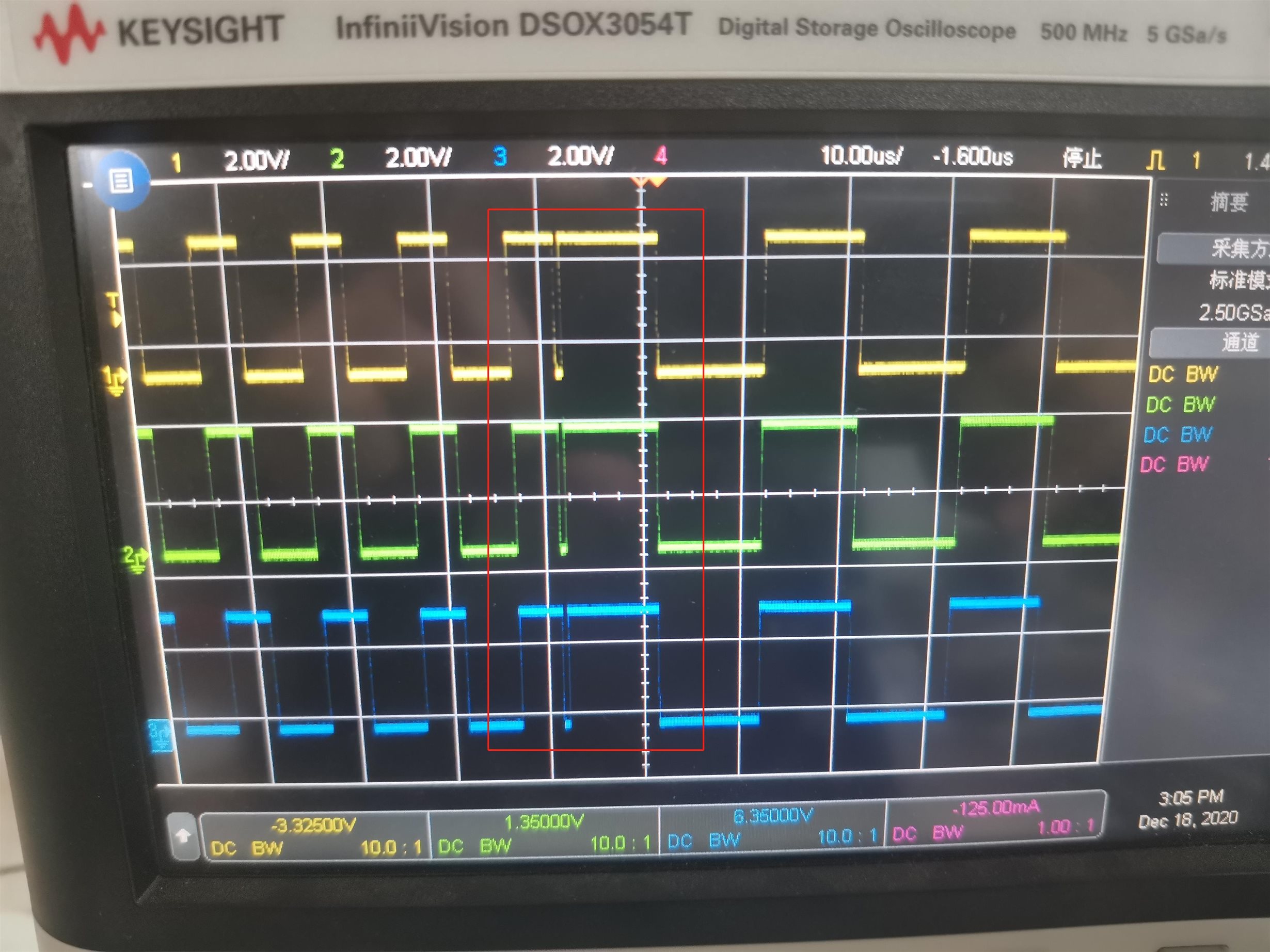
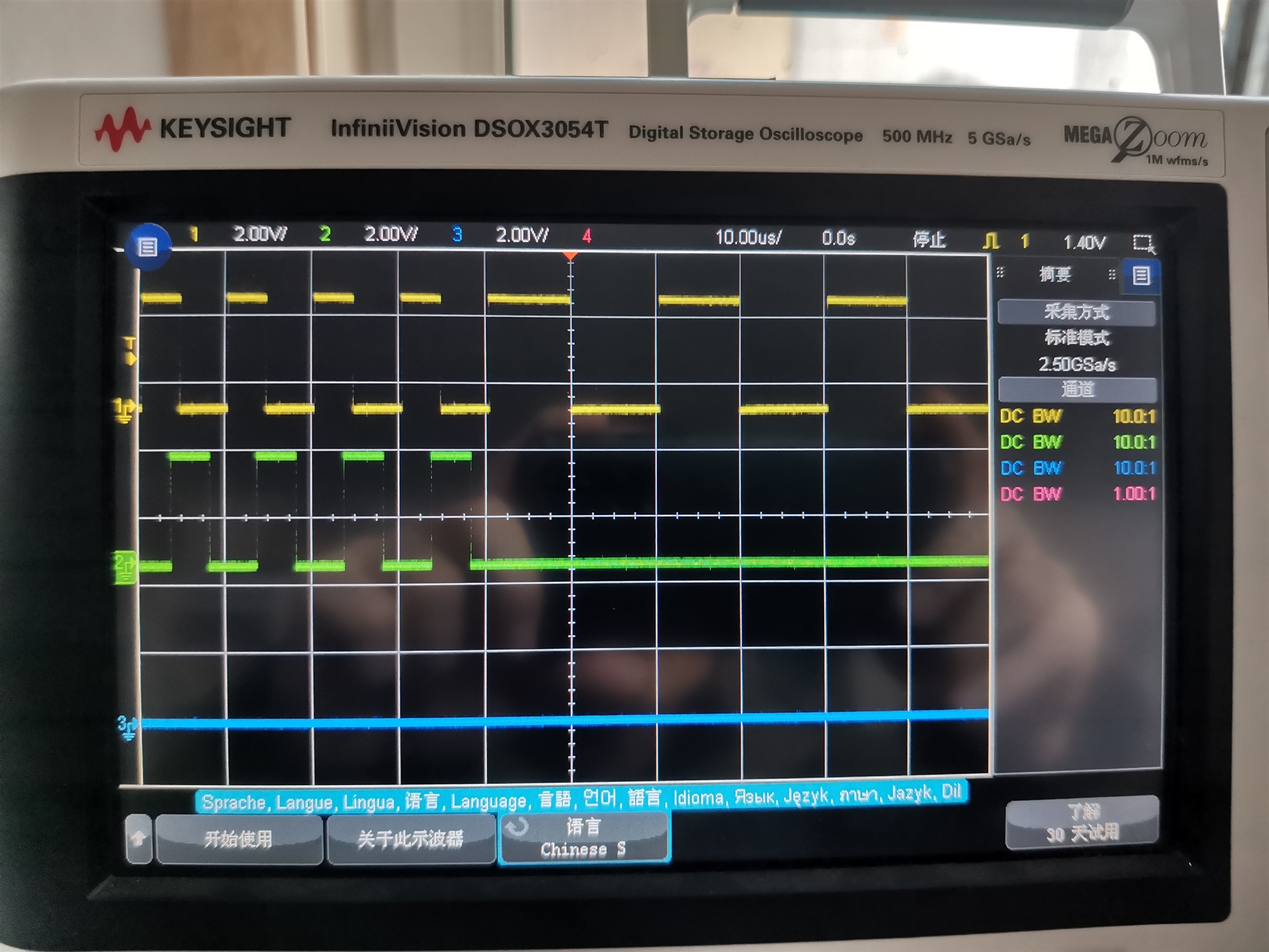
One of my clients encountered a problem in debugging: the output of PWM in the first cycle after frequency conversion (also updated comp value), the configuration code is as follows, the program loads period and compare values from shadow register when CTR = 0.
// =============================================== //
    // === Configure Time Base Submodule Registers === //
    // =============================================== //
    //
    // Enable TBPRD shadow load (Default is load on CTR=0)
    // PWM frequency = 1 / period
    // No phase shift
    // Initialize counter to 0
    // Counter continues to increment during emulation stop
    // Configure counter for up-down count mode
    // Set prescalers: clock divider = 1, HS clock divider = 1
    //
    EPWM_setPeriodLoadMode(base, EPWM_PERIOD_SHADOW_LOAD);
    EPWM_selectPeriodLoadEvent(base, EPWM_SHADOW_LOAD_MODE_COUNTER_ZERO);
    EPWM_setTimeBasePeriod(base, LLC_PERIOD_INIT_TICKS);
    EPWM_setTimeBaseCounter(base, 0);
    EPWM_setEmulationMode(base, EPWM_EMULATION_STOP_AFTER_NEXT_TB);
    EPWM_setTimeBaseCounterMode(base, EPWM_COUNTER_MODE_DOWN);
    EPWM_setClockPrescaler(base, EPWM_CLOCK_DIVIDER_1, EPWM_HSCLOCK_DIVIDER_1);
    //
    // === Action Qualifier SubModule for LLC - PH1/2/3, PRI === //
    //
    EPWM_setActionQualifierShadowLoadMode(base, EPWM_ACTION_QUALIFIER_A, EPWM_AQ_LOAD_ON_CNTR_ZERO);
    EPWM_setActionQualifierShadowLoadMode(base, EPWM_ACTION_QUALIFIER_B, EPWM_AQ_LOAD_ON_CNTR_ZERO);
    EPWM_setActionQualifierAction(base, EPWM_AQ_OUTPUT_A, EPWM_AQ_OUTPUT_LOW,  EPWM_AQ_OUTPUT_ON_TIMEBASE_PERIOD);
    EPWM_setActionQualifierAction(base, EPWM_AQ_OUTPUT_A, EPWM_AQ_OUTPUT_HIGH, EPWM_AQ_OUTPUT_ON_TIMEBASE_DOWN_CMPA);
    EPWM_setActionQualifierAction(base, EPWM_AQ_OUTPUT_A, EPWM_AQ_OUTPUT_HIGH, EPWM_AQ_OUTPUT_ON_TIMEBASE_ZERO);
    EPWM_setActionQualifierAction(base, EPWM_AQ_OUTPUT_B, EPWM_AQ_OUTPUT_LOW,  EPWM_AQ_OUTPUT_ON_TIMEBASE_PERIOD);
    EPWM_setActionQualifierAction(base, EPWM_AQ_OUTPUT_B, EPWM_AQ_OUTPUT_HIGH, EPWM_AQ_OUTPUT_ON_TIMEBASE_DOWN_CMPB);
    EPWM_setActionQualifierAction(base, EPWM_AQ_OUTPUT_B, EPWM_AQ_OUTPUT_HIGH, EPWM_AQ_OUTPUT_ON_TIMEBASE_ZERO);
    //
    // ===================================================== //
    // === Configure Counter Compare Submodule Registers === //
    // ===================================================== //
    //
    // Set initial CMPA value
    // Set initial CMPB value
    // Enable CMPA shadow load on CTR = 0
    // Enable CMPB shadow load on CTR = 0
    //
    EPWM_setCounterCompareShadowLoadMode(base, EPWM_COUNTER_COMPARE_A, EPWM_COMP_LOAD_ON_CNTR_ZERO);
    EPWM_setCounterCompareShadowLoadMode(base, EPWM_COUNTER_COMPARE_B, EPWM_COMP_LOAD_ON_CNTR_ZERO);
    EPWM_setCounterCompareValue(base, EPWM_COUNTER_COMPARE_A, LLC_PERIOD_INIT_TICKS >> 1);
    EPWM_setCounterCompareValue(base, EPWM_COUNTER_COMPARE_B, LLC_PERIOD_INIT_TICKS >> 1);
    //
    // =============================================== //
    // === Configure Dead-Band Submodule Registers === //
    // =============================================== //
    //
    // Active high complementary PWMs - Set up the deadband
    // Enable rising edge delay
    // Enable falling edge delay
    // RED polarity is active high
    // FED polarity is active low (inverted)
    // Enable shadow load on CTR = 0 for RED count
    // Enable shadow load on CTR = 0 for FED count
    //
    EPWM_setDeadBandControlShadowLoadMode(base, EPWM_DB_LOAD_ON_CNTR_ZERO);
    EPWM_setRisingEdgeDeadBandDelayInput(base,  EPWM_DB_INPUT_EPWMA);
    EPWM_setFallingEdgeDeadBandDelayInput(base, EPWM_DB_INPUT_EPWMB);
    EPWM_setDeadBandDelayMode(base, EPWM_DB_RED, true);
    EPWM_setDeadBandDelayMode(base, EPWM_DB_FED, true);
    EPWM_setDeadBandDelayPolarity(base, EPWM_DB_RED, EPWM_DB_POLARITY_ACTIVE_HIGH);
    EPWM_setDeadBandDelayPolarity(base, EPWM_DB_FED, EPWM_DB_POLARITY_ACTIVE_LOW);
    EPWM_setRisingEdgeDelayCountShadowLoadMode(base, EPWM_RED_LOAD_ON_CNTR_ZERO);
    EPWM_setFallingEdgeDelayCountShadowLoadMode(base, EPWM_FED_LOAD_ON_CNTR_ZERO);
    EPWM_setRisingEdgeDelayCount(base,  red);
    EPWM_setFallingEdgeDelayCount(base, fed);
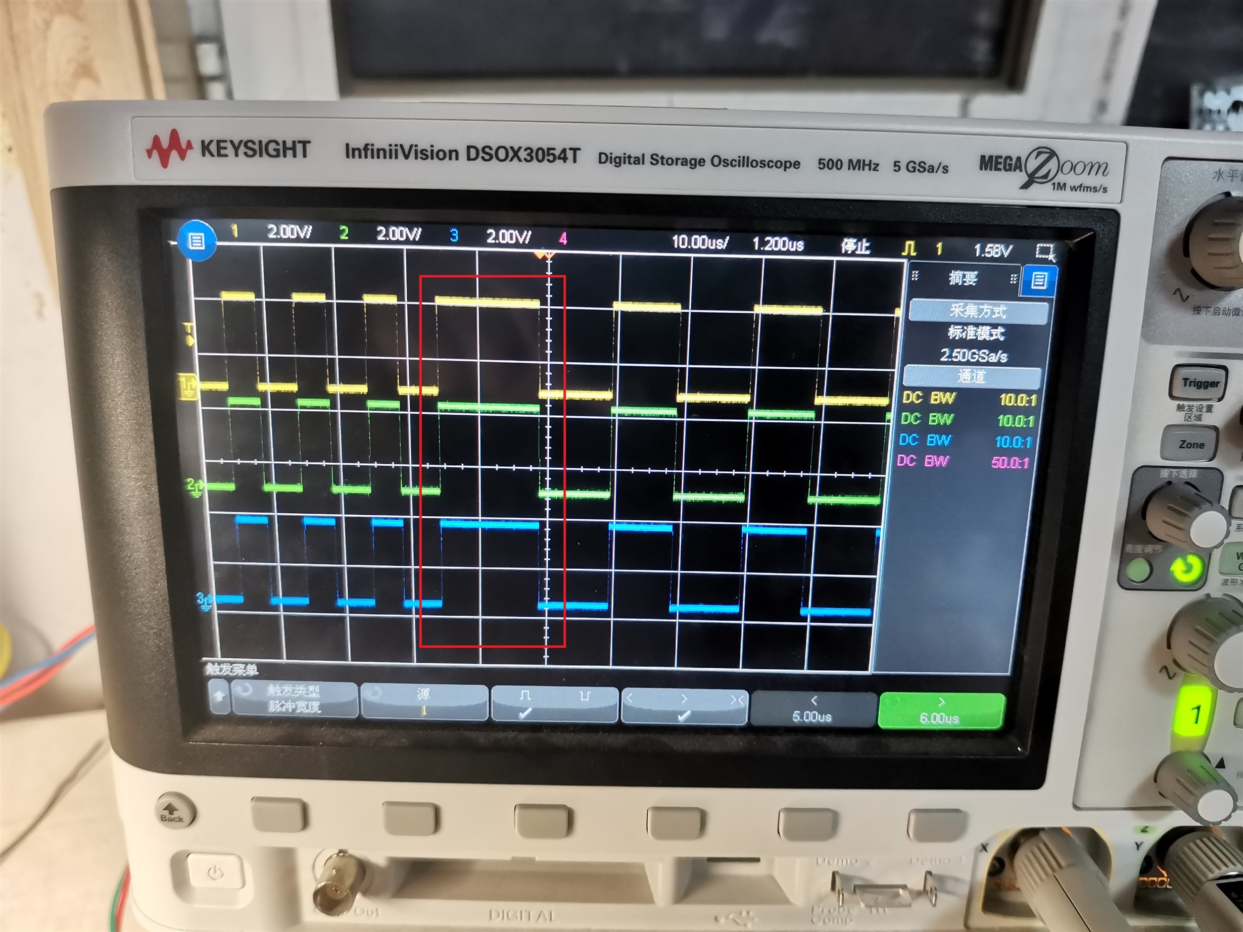
The following figure shows the actual output of PWM. The period in the red box is not the set frequency conversion period, but longer than the expected cycle time:
In addition, I confirm to him that the PRDLD bit in the TBCTL register of PWM is in shadow mode.
Best Regards