This thread has been locked.

If you have a related question, please click the "Ask a related question" button in the top right corner. The newly created question will be automatically linked to this question.

TMS320F28035: Application of HRPWM in up-down mode

Part Number: TMS320F28035

Dear team:

When PWM is in updown mode:

1, If EPwm1Regs.HRCNFG.bit.EDGMODE is set to 0x02 (HR_FEP), since only the falling edge can obtain high resolution, the rising edge can not obtain high resolution, which will lead to the fact that the resolution of PWM is still only 1 / 60m.

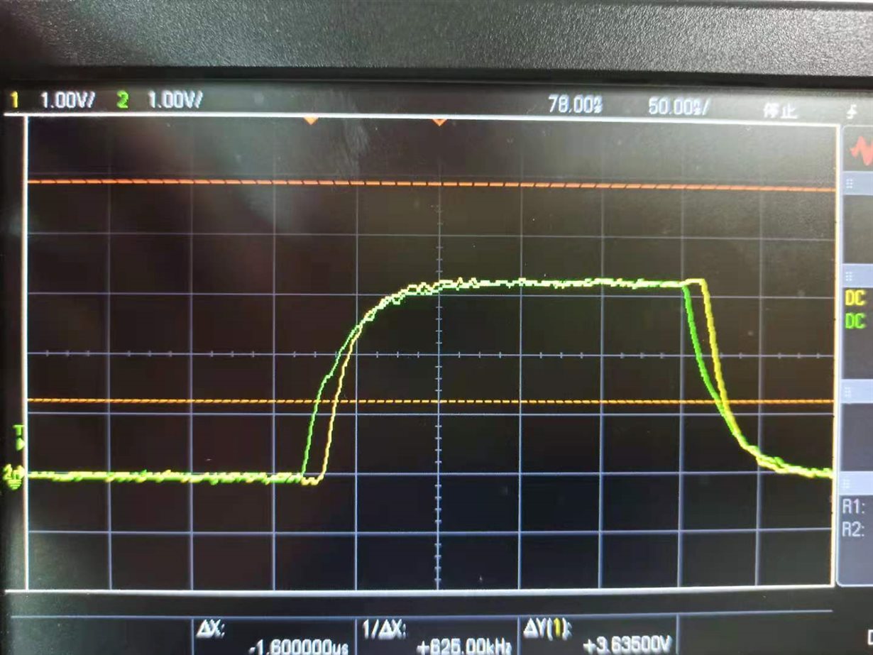
2, If EPwm1Regs.HRCNFG.bit.EDGMODE is set to 0x03 (HR_BEP), in this case, the high-resolution part will be delayed at both the rising edge and the falling edge. That is to say, in the HR_BEP mode, the high-resolution part can only cause phase shift and cannot change the duty cycle.

Is my understanding correct? 

Best Regards

  • Hi Green,

    1. Even if you only apply edge control to the falling edge you will still have a higher resolution than if you disable the HRPWM capability. 

    2. This is true if you set CTLMODE (bit 2 of the HRCNFG register) to 1, meaning the TBPHSHR register controls the edge position. If you set CTLMODE to 0, meaning CMPAHR or TBPRDHR register controls the edge position, then you can change the duty cycle.

    Best Regards,

    Marlyn

  • Dear Marlyn:

    For the second point, my configuration is as follows:

    EALLOW;
    EPwm1Regs.HRCNFG.all = 0x0;
    EPwm1Regs.HRCNFG.bit.EDGMODE = HR_BEP; // MEP control on both edges
    EPwm1Regs.HRCNFG.bit.CTLMODE = HR_CMP;
    EPwm1Regs.HRCNFG.bit.HRLOAD = HR_CTR_PRD;
    
    EPwm1Regs.HRCNFG.bit.AUTOCONV = 1; // Enable autoconversion
    
    EPwm1Regs.HRPCTL.bit.HRPE = 0;
    EDIS;

    For comparison, pwm1 and 2 are set as follows:

    The measured waveforms are as follows:

    Best Regards

  • Hi Green,

    Could you please expand on the issue you are facing?

    Best Regards,

    Marlyn