Tool/software: Code Composer Studio
I use the Ecap1 module with LaunchPad 28379d to measure the pulse wave's duty cycle.
My setting :Cap1 detect rising edge and TSCTR is not count to zero
Cap2 detect falling edge and when Cap2 detect falling edge.The TSCTR is clear and go to interrupt to read value
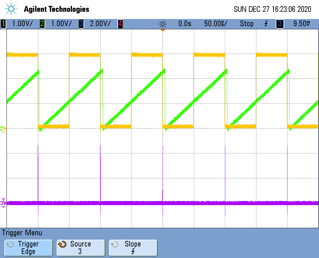
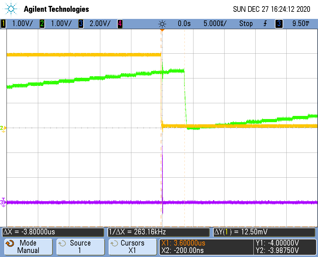
As picture show in below.Yellow is input signal(10kHz ) to gpio24. Purple is interrupt signal. And green is TSCTR which using DAC function to observe.
My question is why TSCTR need to take around 3.8us to be set zero????
=====================code==============================================
#include "F28x_Project.h"
//
// Defines
//
// Configure the start/end period for the timer
#define PWM3_TIMER_MIN 10
#define PWM3_TIMER_MAX 8000
// To keep track of which way the timer value is moving
#define EPWM_TIMER_UP 1
#define EPWM_TIMER_DOWN 0
//
// Globals
//
Uint32 ECap1IntCount;
Uint32 ECap1PassCount;
Uint32 EPwm3TimerDirection;
Uint32 Ecap1ct1;
Uint32 Ecap1ct2;
Uint32 TSCTR;
//=====================DCA==============
#define REFERENCE_VREFHI 1
#define REFERENCE_VREF 1
#define DACA 1
#define DACB 2
#define DACC 3
#define REFERENCE REFERENCE_VREFHI
#define DAC_NUM DACA
volatile struct DAC_REGS* DAC_PTR[4] = {0x0,&DacaRegs,&DacbRegs,&DaccRegs};
//=====================DCA==============
__interrupt void ecap1_isr(void);
void InitECapture(void);
void InitEPwmTimer(void);
void Fail(void);
void ConfigureGPIO(void);
//
// Main
//
void main(void)
{
InitSysCtrl();
InitEPwm3Gpio();
InitECap1Gpio(24);
GPIO_SetupPinOptions(24, GPIO_INPUT, GPIO_SYNC);
ConfigureDAC(DAC_NUM);
ConfigureDAC(DACB);
ConfigureGPIO();
DINT;
InitPieCtrl();
IER = 0x0000;
IFR = 0x0000;
InitPieVectTable();
EALLOW; // This is needed to write to EALLOW protected registers
PieVectTable.ECAP1_INT = &ecap1_isr;
EDIS; // This is needed to disable write to EALLOW protected registers
InitEPwmTimer(); // For this example, only initialize the ePWM Timers
InitECapture();
ECap1IntCount = 0;
ECap1PassCount = 0;
IER |= M_INT4;
PieCtrlRegs.PIEIER4.bit.INTx1 = 1;
EINT; // Enable Global __interrupt INTM
ERTM; // Enable Global realtime __interrupt DBGM
for(;;)
{
TSCTR=ECap1Regs.TSCTR;
DAC_PTR[DAC_NUM]->DACVALS.all =(TSCTR/20030.0)*4096;
DAC_PTR[DACB]->DACVALS.all =(TSCTR/20030.0)*4096;
}
}
void InitEPwmTimer()
{
EALLOW;
CpuSysRegs.PCLKCR0.bit.TBCLKSYNC = 0;
EDIS;
EPwm3Regs.TBCTL.bit.CTRMODE = TB_COUNT_UP; // Count up
EPwm3Regs.TBPRD = PWM3_TIMER_MIN;
EPwm3Regs.TBPHS.all = 0x00000000;
EPwm3Regs.AQCTLA.bit.PRD = AQ_TOGGLE; // Toggle on PRD
EPwm3Regs.TBCTL.bit.HSPCLKDIV = 1;
EPwm3Regs.TBCTL.bit.CLKDIV = 0;
EPwm3TimerDirection = EPWM_TIMER_UP;
EALLOW;
CpuSysRegs.PCLKCR0.bit.TBCLKSYNC = 1;
EDIS;
}
void InitECapture()
{
ECap1Regs.ECEINT.all = 0x0000; // Disable all capture __interrupts
ECap1Regs.ECCLR.all = 0xFFFF; // Clear all CAP __interrupt flags
ECap1Regs.ECCTL1.bit.CAPLDEN = 0; // Disable CAP1-CAP4 register loads
ECap1Regs.ECCTL2.bit.TSCTRSTOP = 0; // Make sure the counter is stopped
ECap1Regs.ECCTL2.bit.CONT_ONESHT = 1; // One-shot
ECap1Regs.ECCTL2.bit.STOP_WRAP = 1; // Stop at 2 events
ECap1Regs.ECCTL1.bit.CAP1POL = 0; // Risingedge
ECap1Regs.ECCTL1.bit.CAP2POL = 1; // Falling edge
ECap1Regs.ECCTL1.bit.CTRRST1 = 0; //Abs
ECap1Regs.ECCTL1.bit.CTRRST2 = 1; // Difference operation
ECap1Regs.ECCTL2.bit.SYNCI_EN = 1; // Enable sync in
ECap1Regs.ECCTL2.bit.SYNCO_SEL = 0; // Pass through
ECap1Regs.ECCTL1.bit.CAPLDEN = 1; // Enable capture units
ECap1Regs.ECCTL2.bit.TSCTRSTOP = 1; // Start Counter
ECap1Regs.ECCTL2.bit.REARM = 1; // arm one-shot
ECap1Regs.ECCTL1.bit.CAPLDEN = 1; // Enable CAP1-CAP4 register loads
ECap1Regs.ECEINT.bit.CEVT2 = 1; // 2 events = __interrupt
}
__interrupt void ecap1_isr(void)
{
GpioDataRegs.GPBSET.bit.GPIO32 = 1;
ECap1PassCount++;
Ecap1ct1=ECap1Regs.CAP1;
Ecap1ct2=ECap1Regs.CAP2;
ECap1Regs.ECCLR.bit.CEVT2 = 1;
ECap1Regs.ECCLR.bit.INT = 1;
ECap1Regs.ECCTL2.bit.REARM = 1;
GpioDataRegs.GPBCLEAR.bit.GPIO32 = 1;
PieCtrlRegs.PIEACK.all = PIEACK_GROUP4;
}
void ConfigureDAC(Uint16 dac_num)
{
EALLOW;
DAC_PTR[dac_num]->DACCTL.bit.DACREFSEL = REFERENCE;
DAC_PTR[dac_num]->DACOUTEN.bit.DACOUTEN = 1;
DAC_PTR[dac_num]->DACCTL.bit.LOADMODE=0;
DAC_PTR[dac_num]->DACVALS.all = 0;
DELAY_US(10); // Delay for buffered DAC to power up
EDIS;
}
void ConfigureGPIO(void)
{
EALLOW;
GpioCtrlRegs.GPBPUD.bit.GPIO32 = 0; // Enable pullup on GPIO34
GpioCtrlRegs.GPBMUX1.bit.GPIO32 = 0; // GPIO34 = GPIO34
GpioCtrlRegs.GPBDIR.bit.GPIO32 = 1; // GPIO34 = output
GpioDataRegs.GPBCLEAR.bit.GPIO32 = 1; // GPIO34 = 1
GpioCtrlRegs.GPAPUD.bit.GPIO18 = 0; // Enable pullup on GPIO34
GpioCtrlRegs.GPAMUX2.bit.GPIO18 = 0; // GPIO34 = GPIO34
GpioCtrlRegs.GPADIR.bit.GPIO18 = 1; // GPIO34 = output
GpioDataRegs.GPACLEAR.bit.GPIO18 = 1; // GPIO34 = 1
EDIS;
}