


Other Parts Discussed in Thread: TMS320F28379D, LAUNCHXL-F28379D
Tool/software: Simulink
Hi,
I'm struggling to read a PWM input using eCAP and would like to request some help.
I'm using Simulink to design my application and all I did so far was using an eCAP block as APWM to generate a PWM output and then connect that same output to the eCAP input to read it.
Unfortunately due to COVID I do not have all the equipment I could use but I can see my PWM is working by simply measuring it with a voltmeter.
My eCAP input is not working though.
My model is very simple:
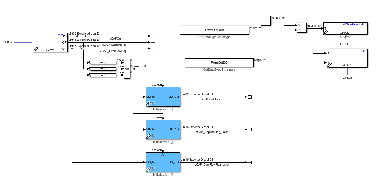
I'm using CCP to monitor those variables and none changes, I can see the overflow flag latching but apart from that, the period is not returned:

I'm not sure what to select in the configuration dialogue for the eCAP block (I tried multiple combinations but none work):

I'm using eCAP4 (random choice of eCAP) and I've set it to GPIO7:
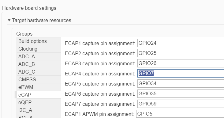
Do I need to configure anything else? Is this capable of reading a 13V pulsing signal or does it need to be 5V? I have my block sampling at 100us.
The documentation is extensive and I can imagine it would make sense to a lot of people, unfortunately I do not have that much in depth knowledge to understand everything that is written there and am struggling with what should be a quite basic operation. In any other platform I've worked with, usually we have a block which we select the pin and it outputs a frequency reading, as simple as that.
I appreciate any help you can provide and apologies if this has been asked before but I couldn't find any information which would apply to the Simulink setup. I know the Simulink blockset is Mathworks area but the parameters/procedure that need to be selected/followed are common and hopefully you can help me with those.
PS: Not sure why the development tool shows CCS but I believe this is due to the fact I started this thread through "Ask a related question". Apologies for misleading you.
Thank you all in advance.
Celso

