This thread has been locked.

If you have a related question, please click the "Ask a related question" button in the top right corner. The newly created question will be automatically linked to this question.

BLDC Sensorless BEMF measurement

Other Parts Discussed in Thread: CONTROLSUITE

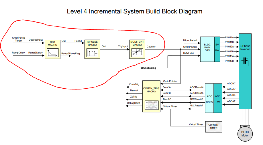
Hello! I am implementing a sensorless BLDC control on a C2000 MCU, following the document found here:

https://www.ti.com/lit/an/sprabz3/sprabz3.pdf?ts=1610192643720&ref_url=https%253A%252F%252Fwww.google.com%252F.

Right now I have problems with measureing the back-emf of my BLDC that is necessary for sensorless control. According to the text in the link above, the BEMF can be obtained by measuring the non-energized phase. I have measured the phase with an oscilloscope, but i have problems interpreting what is going on. Could I get some help here?

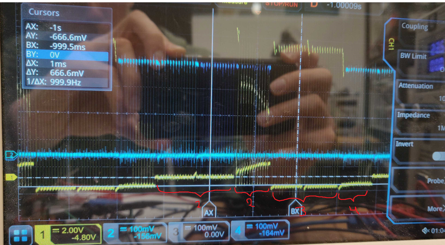
Yellow is the phase measurement (directly on phase, no filtering). Blue and turquoise are the PWMs of the other two phases. During time period 1, the phase that I measure on is energized (lower transistor ON -> zero volts). During time period 2, I suspect I am seeing the BEMF. During 3, the phase is energized again with top transistor PWMed. During time period 4 I do not know what's going on. The voltage is -0.7V during T4.

So I should filter this signal and use it during time period 2? 

  • According to the document above, I should use the equation: 

    I see different values in time period 2 when the PWM is on and off. Which value is the one to be used for BEMF calculation?

  • It seems the startup of sensorless BLDC control is more complex than I thought. What I am doing now is simply switching between commutations to get speed. But I have read now somewhere that I need to accelerate the motor at a certain rate because "The angle between the stator and rotor magnetic fields must be in 90deg±30deg.". Otherwise I won't get a correct measurement of the BEMF.

    Is this what is going on in the TI code modules below?

  • Hi Niclas,

    Thanks for your question. I have looped in the C2000 experts to take a look.

    Thanks,

    Matt

  • You might take a look at the reference design and the application note in the below folder if you downloaded and installed the controlSUITE

    C:\ti\controlSUITE\development_kits\DRV8312-C2-KIT_v128\BLDC_Sensorless

    ControlSUITE: https://www.ti.com/tool/controlsuite

    The BEMF is very low and is difficult to achieve the zero-cross point when the motor is running at a very low speed. So using the RC3 and IMPULSE modules to force the motor to run to a speed using open-loop control, and then switch to the closed-loop using the bemf zero-cross point for commutation.