Hello Champs,
Customer is using F28388S EtherCAT function and has some questions as below:
1) Regarding external EEPROM needed by F28388S ESC, is there any special resource requirement for it such as capacity etc.? Shall we have recommendation for this EEPROM selection?
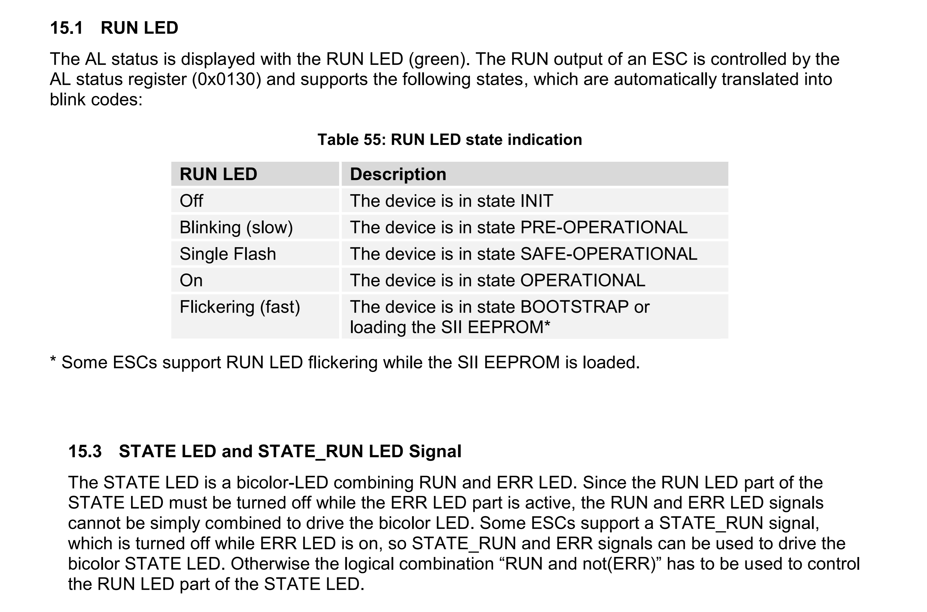
2) What about the difference of pin108 (ECS_LED_STATE_RUN) and pin107 (ECS_LED_RUN)? How to design the connection of pin108?
3) In datasheet pin155 (ECS_TX0_CLK) has been marked with "I" (input), is its direction wrong?
4) Is it OK to use pin90 (ESC_PHY_CLK) as output and provide clock for external PHY chip so that additional external oscillator for PHY chip can be unnecessary?
Would you please kindly help? Thanks!
Best Regards,
Linda