This thread has been locked.

If you have a related question, please click the "Ask a related question" button in the top right corner. The newly created question will be automatically linked to this question.

TMS320F28388D: Use high-resolution period control and phase control together

Part Number: TMS320F28388D
Other Parts Discussed in Thread: C2000WARE

Hello,

I have a question regarding “high resolution PWM”.

My system requires both of the high-resolution period control and phase control at the same time.

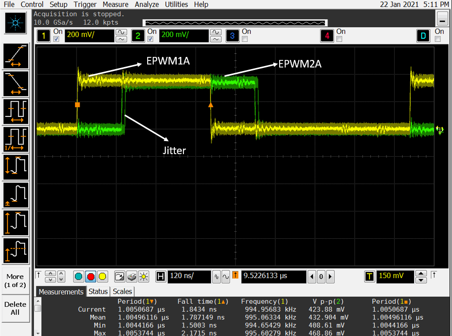
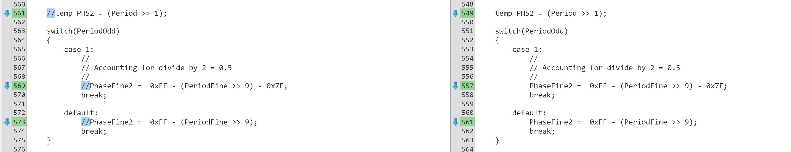
I have examined by the following related code, but the phase shifted epwm2 output has jitter during edging.

when I changed the setting to the following, the jitter disappeared.

EPwm1Regs.TBPRDHR = 0x0;

EPwm2Regs.TBPRDHR = 0x0;

OR

EPwm1Regs.HRPCTL.bit.HRPE = 0U;

EPwm2Regs.HRPCTL.bit.HRPE = 0U;


Is it possible to use high-resolution period control and phase control together?

If possible, is there any problem with my configuration ?


Here is the initialization:

-EPWM clock: 200MHz

-Up –down counter mode

-With TBCTR = 0x0000 event synchronization

-PWM frequency = 995kHz (peak cnt = 100.5)

-Phase shift = 90.5degree (25.5cnt)

A part of the related code:

------------------------------------------------------------------------

do {
status = SFO();
if (status == SFO_ERROR) {
error();
}
} while (status == SFO_INCOMPLETE);
#endif

EALLOW;
/* Timer stop */
CpuSysRegs.PCLKCR0.bit.TBCLKSYNC = 0U;
ClkCfgRegs.PERCLKDIVSEL.bit.EPWMCLKDIV = 0;
CpuSysRegs.PCLKCR2.bit.EPWM1 = 1U;
CpuSysRegs.PCLKCR2.bit.EPWM2 = 1U;
EDIS;

EPwm1Regs.TBCTL.bit.PHSEN = TB_DISABLE;
EPwm2Regs.TBCTL.bit.PHSEN = TB_DISABLE;
EPwm1Regs.TBCTL.bit.CTRMODE = TB_COUNT_UPDOWN;
EPwm2Regs.TBCTL.bit.CTRMODE = TB_COUNT_UPDOWN;

EPwm1Regs.EPWMSYNCINSEL.bit.SEL = 0U;
EPwm1Regs.EPWMSYNCOUTEN.bit.ZEROEN = 1U; //for f28388
EPwm2Regs.EPWMSYNCINSEL.bit.SEL = 1U;
EPwm2Regs.EPWMSYNCOUTEN.bit.ZEROEN = 0U; //for f28388

EPwm1Regs.HRPCTL.bit.TBPHSHRLOADE = 1U;
EPwm2Regs.HRPCTL.bit.TBPHSHRLOADE = 1U;

EPwm1Regs.TBPRD = 100U; // PWM frequency = 1/(2*TBPRD)
EPwm1Regs.TBPRDHR = 0x7F<<8U;
EPwm2Regs.TBPRD = 100U;
EPwm2Regs.TBPRDHR = 0x7F<<8U;

EALLOW;
EPwm1Regs.HRCNFG.bit.EDGMODE = 3U; /** MEP control of both edges (TBPHSHR or TBPRDHR) **/
EPwm1Regs.HRCNFG.bit.CTLMODE = 0U; /** CMPAHR(8) or TBPRDHR(8) Register controls the edge position **/
EPwm1Regs.HRCNFG.bit.HRLOAD = 2U; /** CMPAHR shadow value Load on either CTR = Zero or CTR = PRD **/
EPwm1Regs.HRCNFG.bit.SELOUTB = 0U; /** ePWMxB output is normal?**/
EPwm1Regs.HRCNFG.bit.AUTOCONV = 1U; /** Automatic HRMSTEP scaling is enabled **/
EPwm1Regs.HRCNFG.bit.EDGMODEB = 3U; /** MEP control of both edges (TBPHSHR or TBPRDHR) **/
EPwm1Regs.HRCNFG.bit.HRLOADB = 2U; /** CMPBHR shadow value Load on either CTR = Zero or CTR = PRD **/

EPwm2Regs.HRCNFG.bit.EDGMODE = 3U; /** MEP control of both edges (TBPHSHR or TBPRDHR) **/
EPwm2Regs.HRCNFG.bit.CTLMODE = 0U; /** CMPAHR(8) or TBPRDHR(8) Register controls the edge position **/
EPwm2Regs.HRCNFG.bit.HRLOAD = 2U; /** CMPAHR shadow value Load on either CTR = Zero or CTR = PRD **/
EPwm2Regs.HRCNFG.bit.SELOUTB = 0U; /** ePWMxB output is normal?**/
EPwm2Regs.HRCNFG.bit.AUTOCONV = 1U; /** Automatic HRMSTEP scaling is enabled **/
EPwm2Regs.HRCNFG.bit.EDGMODEB = 3U; /** MEP control of both edges (TBPHSHR or TBPRDHR) **/
EPwm2Regs.HRCNFG.bit.HRLOADB = 2U; /** CMPBHR shadow value Load on either CTR = Zero or CTR = PRD **/

EPwm1Regs.HRPCTL.bit.HRPE = 1U; // highresolutionperiod control is enabled
EPwm2Regs.HRPCTL.bit.HRPE = 1U; // highresolutionperiod control is enabled

EPwm2Regs.TBPHS.bit.TBPHS = 25U;
EPwm2Regs.TRREM.bit.TRREM = 0x17F;
EPwm2Regs.TBCTL.bit.PHSDIR = 0;
EPwm2Regs.TBCTL.bit.PHSEN = TB_ENABLE;

CpuSysRegs.PCLKCR0.bit.TBCLKSYNC = 1U; /* Time Base Clock enable */
EDIS;

  • Hello,

    I am attaching the waveform.

    You will see the jitter in the waveform.

    Dose “Duty Cycle Range Limitation” affect this problem?


    Thank you.


    Best regards,

    Wenjing

  • In general high resolution phase control and high resolution period control dont work together if the SYNC pulse is sent out periodically on every period, you will see jitter. Is having both of these in HR mode a requirement?

  • Thank you for reply.

    If there is an easy way, we would like to have both work together in HR mode.

    If not, we will choose one with HR mode.

    Best Regards,

    Wenjing 

  • We have this example which uses the workaround. Have you looked at it?

    C2000Ware_3_03_00_00\device_support\f2838x\examples\cpu1\hrpwm\hrpwm_ex4_deadband_sfo_v8.c

  • I have looked at this example.

    My understanding is as below.

    In initialization,

    -Force one-time synchronization pulse by SWFSYNC

    -Enable the TBCTR = 0x0000 event to set the EPWM1SYNCOUT signal as the source of the EPWM2SYNCI signal.

    -Turn on high-resolution period control by HRPCTL.bit.HRPE

    -Enable phase load on SYNC of EPWM2.


    I tried to make a simple code based on the example by commenting out the calculations and writing the value directly to TBPRDHR, TBPRD, TBPHS, TRREM.

    For the result, the jitter still appears when writing a little large value to the TBPRDHR.

    If setting zero to TBPRDHR, the jitter will disappears.

    I am attaching the C source, could you confirm and give me any comment on this issue?

    Should I write zero to TBPRDHR, when enabling phase load (TRREM) on SYNC?


    Thank you.


    Best Regards,

    Wenjing

    //###########################################################################
    //
    // FILE:    hrpwm_ex4_deadband_sfo_v8.c
    //
    // TITLE:   f2838x Device HRPWM SFO V8 High-Resolution Dead-Band
    //          (up-down count) example
    //
    //! \addtogroup cpu01_example_list
    //! <h1> HRPWM Dead-Band Example (hrpwm_deadband_sfo_v8)</h1>
    //! This program requires the f2838x header files, including the
    //! following files required for this example:
    //! sfo_v8.h and SFO_v8_fpu_lib_build_c28_eabi.lib
    //!
    //! Monitor ePWM1 & ePWM2 A/B pins on an oscilloscope
    //!
    //! DESCRIPTION:
    //!
    //! This example sweeps the ePWM frequency while maintaining a duty cycle of
    //! ~50% in ePWM up-down count mode. In addition, this example demonstrates
    //! ePWM high-resolution dead-band (HRDB) capabilities utilizing the HRPWM
    //! extension of the respective ePWM module.
    //!
    //! This example calls the following TI's micro-edge positioner (MEP) Scale
    //! Factor Optimizer (SFO) software library V8 functions:
    //!
    //! \b int \b SFO(); \n
    //! updates MEP_ScaleFactor dynamically when HRPWM is in use
    //! updates HRMSTEP register (exists only in EPwm1Regs register space)
    //! which updates MEP_ScaleFactor value
    //! - returns 0 if not complete for the specified channel
    //! - returns 1 when complete for the specified channel
    //! - returns 2 if error: MEP_ScaleFactor is greater than maximum value of 255
    //! (Auto-conversion may not function properly under this condition)
    //!
    //! This example is intended to demonstrate the HRPWM capability to control
    //! the dead-band falling edge delay (FED) and rising edge delay (RED).
    //!
    //! ePWM1 and ePWM2 A/B channels will have fine edge movement due to HRPWM
    //! control.
    //!
    //!=======================================================================
    //! NOTE: For more information on using the SFO software library, see the
    //! f2838x High-Resolution Pulse Width Modulator (HRPWM) Chapter in the
    //! Technical Reference Manual.
    //!=======================================================================
    //!
    //! To load and run this example:
    //! -# **!!IMPORTANT!!**
    //! -# Run this example at maximum SYSCLKOUT
    //! -# Activate Real time mode
    //! -# Run the "AddWatchWindowVars_HRPWM.js" script from the scripting console
    //!    (View -> Scripting Console) to populate watch window by using the
    //!    command:
    //!    loadJSFile <path_to_JS_file>/AddWatchWindowVars_HRPWM.js
    //! -# Run the code
    //! -# Watch ePWM A / B channel waveforms on an oscilloscope
    //! -# In the watch window:
    //!    Change the variable InputPeriodInc to increase or decrease the frequency
    //!    sweep rate. Setting InputPeriodInc = 0 will stop the sweep while
    //!    allowing other variables to be manipulated and updated in real time.
    //! -# In the watch window:
    //!    Change values for registers EPwm1Regs.DBRED/EPwm2Regs.DBRED to see
    //!    changes in rising edge dead-bands for ePWM1 and ePWM2 respectively.
    //!    Alternatively, changing values for registers
    //!    EPwm1Regs.DBFED/EPwm2Regs.DBFED will change falling edge dead-bands for
    //!    ePWM1 and ePWM2. Changing these values will alter the duty cycle
    //!    percentage for their respective ePWM modules.
    //!    **!!NOTE!!** - DBRED/DBFED values should never be set below 4.
    //!                   Do not set these values to 0, 1, 2 or 3.
    //! -# In the watch window:
    //!    Change values for registers
    //!    EPwm1Regs.DBREDHR.bit.DBREDHR/EPwm2Regs.DBREDHR.bit.DBREDHR to increase
    //!    or decrease number of resolvable high-resolution steps at the
    //!    dead-band rising edge. Alternatively, change values for
    //!    EPwm1Regs.DBFEDHR.bit.DBFEDHR/EPwm2Regs.DBFEDHR.bit.DBFEDHR to change
    //!    the number of resolvable steps at the dead-band falling edge for ePWM1
    //!    and ePWM2 respectively.
    //
    //###########################################################################
    // $TI Release: F2838x Support Library v3.03.00.00 $
    // $Release Date: Sun Oct  4 16:00:36 IST 2020 $
    // $Copyright:
    // Copyright (C) 2020 Texas Instruments Incorporated - http://www.ti.com/
    //
    // Redistribution and use in source and binary forms, with or without 
    // modification, are permitted provided that the following conditions 
    // are met:
    // 
    //   Redistributions of source code must retain the above copyright 
    //   notice, this list of conditions and the following disclaimer.
    // 
    //   Redistributions in binary form must reproduce the above copyright
    //   notice, this list of conditions and the following disclaimer in the 
    //   documentation and/or other materials provided with the   
    //   distribution.
    // 
    //   Neither the name of Texas Instruments Incorporated nor the names of
    //   its contributors may be used to endorse or promote products derived
    //   from this software without specific prior written permission.
    // 
    // THIS SOFTWARE IS PROVIDED BY THE COPYRIGHT HOLDERS AND CONTRIBUTORS 
    // "AS IS" AND ANY EXPRESS OR IMPLIED WARRANTIES, INCLUDING, BUT NOT 
    // LIMITED TO, THE IMPLIED WARRANTIES OF MERCHANTABILITY AND FITNESS FOR
    // A PARTICULAR PURPOSE ARE DISCLAIMED. IN NO EVENT SHALL THE COPYRIGHT 
    // OWNER OR CONTRIBUTORS BE LIABLE FOR ANY DIRECT, INDIRECT, INCIDENTAL, 
    // SPECIAL, EXEMPLARY, OR CONSEQUENTIAL DAMAGES (INCLUDING, BUT NOT 
    // LIMITED TO, PROCUREMENT OF SUBSTITUTE GOODS OR SERVICES; LOSS OF USE,
    // DATA, OR PROFITS; OR BUSINESS INTERRUPTION) HOWEVER CAUSED AND ON ANY
    // THEORY OF LIABILITY, WHETHER IN CONTRACT, STRICT LIABILITY, OR TORT 
    // (INCLUDING NEGLIGENCE OR OTHERWISE) ARISING IN ANY WAY OUT OF THE USE 
    // OF THIS SOFTWARE, EVEN IF ADVISED OF THE POSSIBILITY OF SUCH DAMAGE.
    // $
    //###########################################################################
    
    //
    // Included Files
    //
    #include "f28x_project.h"
    #include "sfo_v8.h"
    
    //
    // Defines
    //
    #define PWM_CH              2   // # of PWM channels used in example
    #define HR_ENABLED          1   // 1 = HR behavior
                                    // 0 = non-HR behavior
    
    //
    // Globals
    //
    Uint16 UpdateFine, status;
    Uint16 temp_REM2 = 0, temp_PHS2, PhaseFine2;
    
    Uint32 CountUpdatefine = 0, CountUpdateMax = 0;
    Uint16 Period = 0, PeriodFine = 0, PeriodOdd = 0;
    Uint16 PeriodIncrement = 0, PeriodFineIncrement = 0;
    Uint32 InputPeriodInc = 0;
    Uint32 PeriodFine_temp = 0;
    Uint16 PWM1 = 1;
    Uint16 PWM2 = 2;
    Uint16 PeriodMax = 600, PeriodMin = 360;
    
    //
    // Array of pointers to EPwm register structures:
    // *ePWM[0] is defined as dummy value not used in the example
    //
    volatile struct EPWM_REGS *ePWM[PWM_CH + 1] = {0, &EPwm1Regs, &EPwm2Regs};
    
    int MEP_ScaleFactor;
    
    //
    // Function Prototypes
    //
    void HRPWM1_Config(int);
    void HRPWM2_Config(int);
    void FreqCtl_func(void);
    interrupt void PRDEQfix_ISR(void);
    void error(void);
    
    //
    // Main
    //
    void main(void)
    {
        //
        // Initialize System Control for Control and Analog Subsystems.
        // Enable Peripheral Clocks.
        // This example function is found in the f2838x_SysCtrl.c file.
        //
        InitSysCtrl();
    
        //
        // Disable CPU interrupts
        //
        DINT;
    
        //
        // Initialize the PIE control registers to their default state.
        // The default state is all PIE interrupts disabled and flags
        // are cleared.
        // This function is found in the f2838x_PieCtrl.c file.
        //
        InitPieCtrl();
    
        //
        // Disable CPU interrupts and clear all CPU interrupt flags
        //
        IER = 0x0000;
        IFR = 0x0000;
    
        //
        // Initialize the PIE vector table with pointers to the shell Interrupt
        // Service Routines (ISR).
        // This will populate the entire table, even if the interrupt
        // is not used in this example. This is useful for debug purposes.
        // The shell ISR routines are found in f2838x_defaultisr.c.
        // This function is found in f2838x_PieVect.c.
        //
        InitPieVectTable();
    
        //
        // Set address of ISR in PIE vector table
        //
        EALLOW;
        PieVectTable.EPWM1_INT = &PRDEQfix_ISR;
        EDIS;
    
        //
        // Calling SFO() updates the HRMSTEP register with calibrated
        // MEP_ScaleFactor. HRMSTEP must be populated with a scale factor value
        // prior to enabling high resolution period control.
        //
        status = SFO_INCOMPLETE;
        while(status == SFO_INCOMPLETE)
        {
            //
            // Call until complete
            //
            status = SFO();
            if(status == SFO_ERROR)
            {
                error();
            }
        }
    
        EALLOW;
        CpuSysRegs.PCLKCR0.bit.TBCLKSYNC = 0;
        EDIS;
    
        //
        // Init HRPWM1/HRPWM2
        //
        InitEPwm1Gpio();
        InitEPwm2Gpio();
        HRPWM1_Config(360);  // EPwm1 target, Period = 360
        HRPWM2_Config(360);  // EPwm2 target, Period = 360
    
        EALLOW;
        CpuSysRegs.PCLKCR0.bit.TBCLKSYNC = 1;  // Resync PWM timebase clock
        (*ePWM[PWM1]).GLDCTL2.bit.OSHTLD = 1;  // This should also write to
                                               // GLDCTL2 of PWM2
        EDIS;
    
        //
        // Configure ePWM1 to generate interrupts on period match
        //
        (*ePWM[PWM1]).ETSEL.bit.INTSEL = 1;   // Interrupt on counter zero match
        (*ePWM[PWM1]).ETSEL.bit.INTEN = 1;    // Enable peripheral interrupt
        (*ePWM[PWM1]).ETPS.bit.INTPRD = 1;    // Generate interrupt on every event
        PieCtrlRegs.PIEIER3.bit.INTx1 = 1;    // Enable ePWM1 interrupt in PIE
    
        IER |= 0x0004;                        // Enable core INT #3
        EINT;                                 // Clear global interrupt mask
    
        UpdateFine = 1;                       // Disable continuous updates
        Period = 360;
        PeriodFine = 0x0;
        CountUpdateMax = 0x0FFFF;
        CountUpdatefine = CountUpdateMax;
    
        //
        // Watch window variable to modify the rate of the frequency sweep
        //
        InputPeriodInc = 6553;
    
        for(;;)
        {
            if(Period % 2 == 1)
            {
               PeriodOdd = 1;
             }
             else
             {
                PeriodOdd = 0;
              }
              FreqCtl_func();
    #if 0
            while(UpdateFine == 0)
            {
                if(CountUpdatefine >= CountUpdateMax)
                {
                    if(Period < PeriodMax)
                    {
                        //
                        // Perform sweep
                        //
                        PeriodIncrement = InputPeriodInc >> 16;
                        PeriodFineIncrement = (Uint16)InputPeriodInc;
                        Period = Period + PeriodIncrement;
                        PeriodFine_temp = (Uint32)PeriodFine +
                                                     (Uint32)PeriodFineIncrement;
                        if(PeriodFine_temp >= 0x10000)
                        {
                            PeriodFine_temp = PeriodFine_temp - 0x10000;
                            Period = Period + 1;
                        }
    
                        //
                        // Period is odd - CMP is divide by 2 for 50% duty
                        //
                        if(Period % 2 == 1)
                        {
                            PeriodOdd = 1;
                        }
                        else
                        {
                            PeriodOdd = 0;
                        }
    
                        PeriodFine = (Uint16) PeriodFine_temp;
    
                        //
                        // Update PWM values for non-zero increment
                        //
                        if(InputPeriodInc != 0)
                        {
                            FreqCtl_func();
                        }
                    }
                    else
                    {
                        Period = PeriodMin;
                        PeriodFine = 0;
                        if(InputPeriodInc != 0)
                        {
                            FreqCtl_func();
                        }
                    }
                    CountUpdatefine = 0;
                }
                CountUpdatefine++;
            }
    #endif
        }
    
    }
    
    //
    // HRPWM1_Config - ePWM1 register configuration with HRPWM
    //                 ePWM1A toggle low/high with MEP control on Rising edge
    //
    void HRPWM1_Config(PeriodConfig)
    {
        (*ePWM[PWM1]).TBCTL.bit.PRDLD = TB_SHADOW;  // Set shadow load
    
        //
        // PWM frequency = 1 / PeriodConfig
        //
        (*ePWM[PWM1]).TBPRD = PeriodConfig;
    
        //
        // Set duty 50% initially and initialize HRPWM extension
        //
        (*ePWM[PWM1]).CMPA.bit.CMPA = PeriodConfig / 2;
        (*ePWM[PWM1]).CMPA.bit.CMPAHR = (1 << 8);
        (*ePWM[PWM1]).CMPB.bit.CMPB = PeriodConfig / 2;
        (*ePWM[PWM1]).CMPB.bit.CMPBHR = (1 << 8);
        (*ePWM[PWM1]).TBPHS.all = 0;
        (*ePWM[PWM1]).TBCTR = 0;
    
        (*ePWM[PWM1]).TBCTL.bit.CTRMODE = TB_COUNT_UPDOWN;
        (*ePWM[PWM1]).TBCTL.bit.PHSEN = TB_DISABLE;   // ePWM1 is the Master
        (*ePWM[PWM1]).EPWMSYNCINSEL.all = SYNC_IN_SRC_DISABLE_ALL;
        (*ePWM[PWM1]).EPWMSYNCOUTEN.all = 2;          // syncout on ctr = zero
        (*ePWM[PWM1]).TBCTL.bit.HSPCLKDIV = TB_DIV1;
        (*ePWM[PWM1]).TBCTL.bit.CLKDIV = TB_DIV1;
    
        //
        // LOAD CMPA on CTR = ZERO_PRD
        //
        (*ePWM[PWM1]).CMPCTL.bit.LOADAMODE = CC_CTR_ZERO_PRD;
        (*ePWM[PWM1]).CMPCTL.bit.LOADBMODE = CC_CTR_ZERO_PRD;
    
        (*ePWM[PWM1]).CMPCTL.bit.SHDWAMODE = CC_SHADOW;
        (*ePWM[PWM1]).CMPCTL.bit.SHDWBMODE = CC_SHADOW;
    
        (*ePWM[PWM1]).AQCTLA.bit.CAU = AQ_SET;
        (*ePWM[PWM1]).AQCTLA.bit.CAD = AQ_CLEAR;
    
        EALLOW;
    #if HR_ENABLED
        (*ePWM[PWM1]).HRCNFG.all = 0x1353;
    
        //
        // Turn on high-resolution period control
        //
        (*ePWM[PWM1]).HRPCTL.bit.HRPE = 1;
    
        //
        // Synchronize high resolution phase to start HR period
        //
        (*ePWM[PWM1]).TBCTL.bit.SWFSYNC = 1;
    #endif
    
        (*ePWM[PWM1]).GLDCFG.bit.CMPA_CMPAHR = 1;
        (*ePWM[PWM1]).GLDCFG.bit.CMPB_CMPBHR = 1;
    
        //
        // Load on CTR = ZERO_PRD (2) / ZERO (1)
        //
        (*ePWM[PWM1]).GLDCTL.bit.GLDMODE = 2;
    
        //
        // One shot mode and global load enabled
        //
        (*ePWM[PWM1]).GLDCTL.bit.OSHTMODE = 1;
        (*ePWM[PWM1]).GLDCTL.bit.GLD = 1;
    
        //
        // Write to PWM1 GLDCTL2 will result in simultaneous write to PWM2 GLDCTL2
        //
        (*ePWM[PWM1]).EPWMXLINK.bit.GLDCTL2LINK = PWM1 - 1;
        (*ePWM[PWM1]).DBCTL.bit.OUT_MODE = DB_FULL_ENABLE;
        (*ePWM[PWM1]).DBCTL.bit.POLSEL = DB_ACTV_HIC;
        (*ePWM[PWM1]).DBCTL.bit.IN_MODE = DBA_ALL;
        (*ePWM[PWM1]).DBCTL.bit.SHDWDBREDMODE = 1;
        (*ePWM[PWM1]).DBCTL.bit.SHDWDBFEDMODE = 1;
        (*ePWM[PWM1]).DBCTL.bit.LOADREDMODE = 0;    // Load on Counter == 0
        (*ePWM[PWM1]).DBCTL.bit.LOADFEDMODE = 0;    // Load on Counter == 0
        (*ePWM[PWM1]).DBCTL.bit.HALFCYCLE = 1;
        (*ePWM[PWM1]).DBRED.bit.DBRED = 4;
        (*ePWM[PWM1]).DBREDHR.bit.DBREDHR = 0x0;
        (*ePWM[PWM1]).DBFED.bit.DBFED = 4;
        (*ePWM[PWM1]).DBFEDHR.bit.DBFEDHR = 0x0;
    
        (*ePWM[PWM1]).HRCNFG2.bit.EDGMODEDB = HR_BEP;    // DBREDHR and DBFEDHR
        (*ePWM[PWM1]).HRCNFG2.bit.CTLMODEDBRED = 0;      // Load on ZRO
        (*ePWM[PWM1]).HRCNFG2.bit.CTLMODEDBFED = 0;      // Load on ZRO
        (*ePWM[PWM1]).DBREDHR.bit.DBREDHR = (0 << 9);
    
        EDIS;
    }
    
    //
    // HRPWM2_Config - ePWM2 register configuration with HRPWM
    //                 ePWM2A toggle low/high with MEP control on Rising edge
    //
    void HRPWM2_Config(PeriodConfig)
    {
        (*ePWM[PWM2]).TBCTL.bit.PRDLD = TB_SHADOW;  // Set shadow load
    
        //
        // PWM frequency = 1 / PeriodConfig
        //
        (*ePWM[PWM2]).TBPRD = PeriodConfig;
    
        //
        // Set duty 50% initially and initialize HRPWM extension
        //
        (*ePWM[PWM2]).CMPA.bit.CMPA = PeriodConfig / 2;
        (*ePWM[PWM2]).CMPA.bit.CMPAHR = (1 << 8);
        (*ePWM[PWM2]).CMPB.bit.CMPB = PeriodConfig / 2;
        (*ePWM[PWM2]).CMPB.bit.CMPBHR = (1 << 8);
        (*ePWM[PWM2]).TBPHS.all = 0;
        (*ePWM[PWM2]).TBCTR = 0;
    
        (*ePWM[PWM2]).TBCTL.bit.CTRMODE = TB_COUNT_UPDOWN;
        (*ePWM[PWM2]).TBCTL.bit.PHSEN = TB_DISABLE;   // ePWM1 is the Master
        (*ePWM[PWM2]).EPWMSYNCINSEL.all = SYNC_IN_SRC_SYNCOUT_EPWM1;
        (*ePWM[PWM2]).EPWMSYNCOUTEN.all = 1;          // syncout on ctr = zero
        (*ePWM[PWM2]).TBCTL.bit.HSPCLKDIV = TB_DIV1;
        (*ePWM[PWM2]).TBCTL.bit.CLKDIV = TB_DIV1;
    
        //
        // LOAD CMPA on CTR = 0
        //
        (*ePWM[PWM2]).CMPCTL.bit.LOADAMODE = CC_CTR_ZERO_PRD;
        (*ePWM[PWM2]).CMPCTL.bit.LOADBMODE = CC_CTR_ZERO_PRD;
        (*ePWM[PWM2]).CMPCTL.bit.SHDWAMODE = CC_SHADOW;
        (*ePWM[PWM2]).CMPCTL.bit.SHDWBMODE = CC_SHADOW;
    
        (*ePWM[PWM2]).AQCTLA.bit.CAU = AQ_SET;
        (*ePWM[PWM2]).AQCTLA.bit.CAD = AQ_CLEAR;
    
        EALLOW;
    #if HR_ENABLED
        (*ePWM[PWM2]).HRCNFG.all = 0x1353;
    
        //
        // Turn on high-resolution period control
        //
        (*ePWM[PWM2]).HRPCTL.bit.HRPE = 1;
    
        //
        // Synchronize high resolution phase to start HR period
        //
        (*ePWM[PWM2]).TBCTL.bit.SWFSYNC = 1;
    #endif
    
        (*ePWM[PWM2]).TBCTL.bit.PHSDIR = 1;        // Count up after SYNC event
        (*ePWM[PWM2]).TBPHS.bit.TBPHS = 180;
    
        (*ePWM[PWM2]).GLDCFG.bit.CMPA_CMPAHR = 1;
        (*ePWM[PWM2]).GLDCFG.bit.CMPB_CMPBHR = 1;
    
        //
        // Load on CTR = ZERO_PRD (2) / ZERO (1)
        //
        (*ePWM[PWM2]).GLDCTL.bit.GLDMODE = 2;
    
        //
        // One shot mode and global load enabled
        //
        (*ePWM[PWM2]).GLDCTL.bit.OSHTMODE = 1;
        (*ePWM[PWM2]).GLDCTL.bit.GLD = 1;
    
        //
        // Write to PWM1 GLDCTL2 will result in simultaneous write to PWM2 GLDCTL2
        //
        (*ePWM[PWM2]).EPWMXLINK.bit.GLDCTL2LINK = PWM1 - 1;
        (*ePWM[PWM2]).DBCTL.bit.OUT_MODE = DB_FULL_ENABLE;
        (*ePWM[PWM2]).DBCTL.bit.POLSEL = DB_ACTV_HIC;
        (*ePWM[PWM2]).DBCTL.bit.IN_MODE = DBA_ALL;
        (*ePWM[PWM2]).DBCTL.bit.SHDWDBREDMODE = 1;
        (*ePWM[PWM2]).DBCTL.bit.SHDWDBFEDMODE = 1;
        (*ePWM[PWM2]).DBCTL.bit.LOADREDMODE = 0;    // Load on Counter == 0
        (*ePWM[PWM2]).DBCTL.bit.LOADFEDMODE = 0;    // Load on Counter == 0
        (*ePWM[PWM2]).DBCTL.bit.HALFCYCLE = 1;
        (*ePWM[PWM2]).DBRED.bit.DBRED = 4;
        (*ePWM[PWM2]).DBREDHR.bit.DBREDHR = 0x0;
        (*ePWM[PWM2]).DBFED.bit.DBFED = 4;
        (*ePWM[PWM2]).DBFEDHR.bit.DBFEDHR = 0x0;
    
        (*ePWM[PWM2]).HRCNFG2.bit.EDGMODEDB = HR_BEP;    // DBREDHR and DBFEDHR
        (*ePWM[PWM2]).HRCNFG2.bit.CTLMODEDBRED = 0;      // Load on ZRO
        (*ePWM[PWM2]).HRCNFG2.bit.CTLMODEDBFED = 0;      // Load on ZRO
        (*ePWM[PWM2]).DBREDHR.bit.DBREDHR = (0 << 9);
    
        EDIS;
    }
    
    //
    // FreqCtl_func - Frequency modulation & phase sync function
    // This function is called only if frequency sweep is enabled
    //
    void FreqCtl_func(void)
    {
        if(PeriodOdd)
        {
            //
            // Add 0.5 if period is odd
            //
            (*ePWM[PWM1]).CMPA.bit.CMPAHR = (PeriodFine >> 1) + 0x7FFF;
            (*ePWM[PWM2]).CMPA.bit.CMPAHR = (PeriodFine >> 1) + 0x7FFF;
            (*ePWM[PWM1]).CMPB.bit.CMPBHR = (PeriodFine >> 1) + 0x7FFF;
            (*ePWM[PWM2]).CMPB.bit.CMPBHR = (PeriodFine >> 1) + 0x7FFF;
        }
        else
        {
            (*ePWM[PWM1]).CMPA.bit.CMPAHR = PeriodFine >> 1;
            (*ePWM[PWM2]).CMPA.bit.CMPAHR = PeriodFine >> 1;
            (*ePWM[PWM1]).CMPB.bit.CMPBHR = PeriodFine >> 1;
            (*ePWM[PWM2]).CMPB.bit.CMPBHR = PeriodFine >> 1;
        }
    
        (*ePWM[PWM1]).CMPA.bit.CMPA = (Period >> 1) + 1;
        (*ePWM[PWM2]).CMPA.bit.CMPA = (Period >> 1) + 1;
        (*ePWM[PWM1]).CMPB.bit.CMPB = (Period >> 1) + 1;
        (*ePWM[PWM2]).CMPB.bit.CMPB = (Period >> 1) + 1;
    
        //temp_PHS2 = (Period >> 1);
    
        switch(PeriodOdd)
        {
            case 1:
                //
                // Accounting for divide by 2 = 0.5
                //
                //PhaseFine2 =  0xFF - (PeriodFine >> 9) - 0x7F;
                break;
    
            default:
                //PhaseFine2 =  0xFF - (PeriodFine >> 9);
                break;
        }
    
        //
        // No fractional phase shift to account for
        //
        temp_REM2 =  (Uint16) 0x100 + PhaseFine2;
        UpdateFine = 1;
    }
    
    //
    // PRDEQfix_ISR - ISR for Translator remainder calculations
    //
    interrupt void PRDEQfix_ISR(void)
    {
        EALLOW;
        if(UpdateFine == 1)
        {
            //
            // This should also write to GLDCTL2 of PWM2, PWM3 and PWM4
            //
            (*ePWM[PWM1]).GLDCTL2.bit.OSHTLD = 1;
    
            //
            // TBCTR phase load on SYNC (required for updown count HR control)
            //
            (*ePWM[PWM2]).TBCTL.bit.PHSEN = TB_ENABLE;
    
            //
            // Coarse phase offset relative to ePWM1
            //
            (*ePWM[PWM2]).TBPHS.bit.TBPHS = temp_PHS2;
            (*ePWM[PWM2]).TRREM.bit.TRREM = temp_REM2;
    
            (*ePWM[PWM2]).TBPRDHR = PeriodFine;
            (*ePWM[PWM2]).TBPRD = Period;
    
            (*ePWM[PWM1]).TBPRDHR = PeriodFine;
            (*ePWM[PWM1]).TBPRD = Period;
            (*ePWM[PWM1]).TRREM.bit.TRREM = 0x100;
            //UpdateFine = 0;
        }
        else
        {
            (*ePWM[PWM2]).TBCTL.bit.PHSEN = TB_DISABLE;
        }
    
        //
        // Re-initialize for next PWM interrupt
        //
        PieCtrlRegs.PIEACK.all = PIEACK_GROUP3;     // Acknowledge PIE interrupt
        (*ePWM[PWM1]).ETCLR.bit.INT = 1;            // Clear interrupt bit
        EDIS;
    }
    
    void error (void)
    {
        ESTOP0;                                     // Stop here and handle error
    }
    
    //
    // End of file
    //
    

  • Let me take a look at your code and I'll get back to you.

    Nima

  • These lines of code are necessary. Using HRPWM in both phase and period mode REQUIRES to follow this specific instructions.

    If you don't, you will get issues with jitters. In general if one of the HRPRD or HRPHS requirement can be removed, go ahead and just use one of the mode.

    This ensure that updateFine is set and used when necessary.