This thread has been locked.

If you have a related question, please click the "Ask a related question" button in the top right corner. The newly created question will be automatically linked to this question.

TMS320F28035: EMI over spec on 120Mhz & 240Mhz

Part Number: TMS320F28035

My customer board base on F28035 report the Radiated EMI over spec on 120Mhz & 240Mhz. Below is the test data for reference.
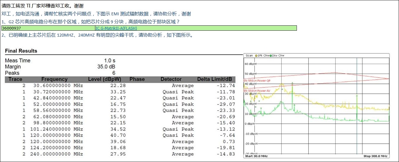
Customer detect the most radiating noise close at pin70 VDDIO by using near field probes. However each Vddio/Vcc pin already connected 2.2uf and 0.1uf cap close to the pin which should meet datasheet requirement. 

We suspect the issue caused by F28035 internal PLL circuit because we config the device CLOCK as 60Mhz. Customer would like to know the internal PLL circuit is placed close to which pin of F28035? So that they can try layout the wire far way the PLL circuit.   

  • However each Vddio/Vcc pin already connected 2.2uf and 0.1uf cap close to the pin which should meet datasheet requirement.

    The datasheet guideline is provided from the perspective of the on-chip VREG. The values may need to fine-tuned based on the operating profile of the application, which is highly application dependent. Power-supply decoupling is a fairly complex topic, but many online resources are available.

    We suspect the issue caused by F28035 internal PLL circuit because we config the device CLOCK as 60Mhz.

    What is the PLL output? Is it 120 MHz that is subsequently divided by 2 to produce 60 MHz? If so, can you try 60 MHz output?

    Customer would like to know the internal PLL circuit is placed close to which pin of F28035? So that they can try layout the wire far way the PLL circuit.

    The PLL is close to X1/X2 pins, so not near pin 70. Pin 36 is also VDDIO. Is emissions excessive near that pin also?