This thread has been locked.

If you have a related question, please click the "Ask a related question" button in the top right corner. The newly created question will be automatically linked to this question.

TMS320F280049: Safety manual ePWM Fault Detection Using XBAR

Part Number: TMS320F280049

Hi,

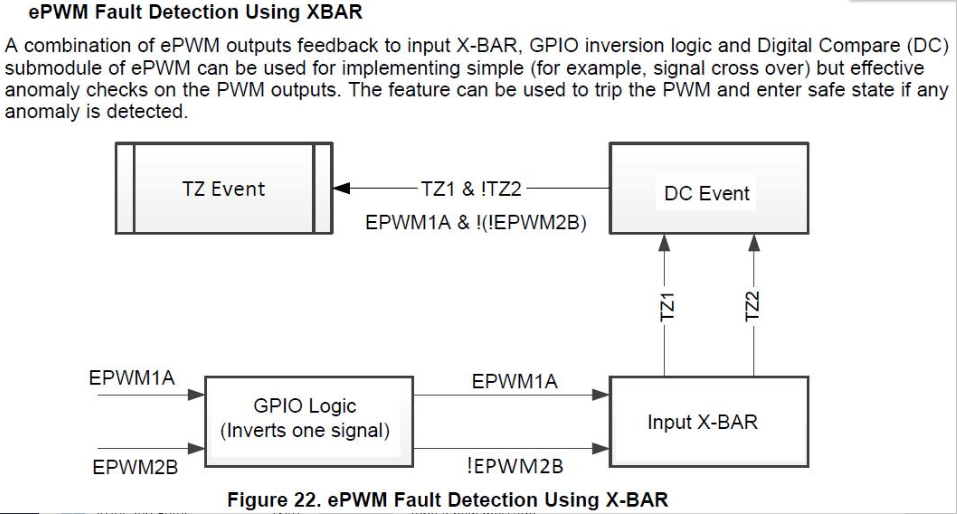
there is mentioned a following feature "ePWM Fault Detection Using XBAR" in safety manual SPRUI78C. Is there any example how to do this in order to save time? Thank you
  • Hi Juraj, 

    This is not one of the use cases that we cover in our standard examples, because the implementation would be expected to have application specific dependencies in order to be useful.  

    Do you have a specific question or a clarification that you need? 

    Thanks,
    Krishna 

  • Hi,

    thanks for the answer.

    My question is if we can do this as oneshot tripzone or can it be only cycle by cycle?

    How exactly you configure TZ1 & !TZ2 part? Is it like:

    TZ1 -> EPWM_DC_TYPE_DCAH

    TZ2 -> EPWM_DC_TYPE_DCAL

    and then configure:

    EPWM_TZ_DC_OUTPUT_A1 -> EPWM_TZ_EVENT_DCXL_HIGH_DCXH_LOW

    Or how? Because this does not work for me.

    Anyway I dont understand how to handle state when PWM output is turned off and both PWMs are in zero, because it also triggers tripzone and it makes impossible to start.

  • Hi Juraj, 

    Thanks for your feedback.  We are in the process of locating the right domain expert to assist you.  We will get back to you shortly.

    Cheers!

    Krishna 

  • Yes you would configure your EPWM DC module to output an event on DCxH and DCyL then grab that DCEVT and pass it to OST or CBC logic, whichever one you want.

    Nima

  • Hi,

    Thanks for answer.

    Well, I tried, but it does not work for me. Here is what I configured:


    GPIO_setPadConfig(1,   GPIO_PIN_TYPE_STD);
    GPIO_setPadConfig(12, GPIO_PIN_TYPE_INVERT);

    XBAR_setInputPin(XBAR_INPUT1,  1U);
    XBAR_setInputPin(XBAR_INPUT2, 12U);

        EPWM_enableDigitalCompareTripCombinationInput(EPWM7_BASE, EPWM_DC_COMBINATIONAL_TRIPIN1, EPWM_DC_TYPE_DCAL);
        //EPWM_enableDigitalCompareTripCombinationInput(EPWM7_BASE, EPWM_DC_COMBINATIONAL_TRIPIN3, EPWM_DC_TYPE_DCBL);
        EPWM_enableDigitalCompareTripCombinationInput(EPWM7_BASE, EPWM_DC_COMBINATIONAL_TRIPIN2, EPWM_DC_TYPE_DCAH);
        //EPWM_enableDigitalCompareTripCombinationInput(EPWM7_BASE, EPWM_DC_COMBINATIONAL_TRIPIN6, EPWM_DC_TYPE_DCBH);
        EPWM_setTripZoneDigitalCompareEventCondition(EPWM7_BASE, EPWM_TZ_DC_OUTPUT_A2, EPWM_TZ_EVENT_DCXL_HIGH_DCXH_LOW);
        //EPWM_setTripZoneDigitalCompareEventCondition(EPWM7_BASE, EPWM_TZ_DC_OUTPUT_B2, EPWM_TZ_EVENT_DCXL_LOW);
        EPWM_setDigitalCompareEventSource(EPWM7_BASE, EPWM_DC_MODULE_A, EPWM_DC_EVENT_2, EPWM_DC_EVENT_SOURCE_ORIG_SIGNAL);
        //EPWM_setDigitalCompareEventSource(EPWM7_BASE, EPWM_DC_MODULE_B, EPWM_DC_EVENT_2, EPWM_DC_EVENT_SOURCE_ORIG_SIGNAL);
        EPWM_setDigitalCompareEventSyncMode(EPWM7_BASE, EPWM_DC_MODULE_A, EPWM_DC_EVENT_2, EPWM_DC_EVENT_INPUT_NOT_SYNCED);
        //EPWM_setDigitalCompareEventSyncMode(EPWM7_BASE, EPWM_DC_MODULE_B, EPWM_DC_EVENT_2, EPWM_DC_EVENT_INPUT_NOT_SYNCED);
        EPWM_setTripZoneAction(EPWM7_BASE, EPWM_TZ_ACTION_EVENT_TZA, EPWM_TZ_ACTION_LOW);  // Configure ePWMxA to output LOW on TZB TRIP
        //EPWM_setTripZoneAction(ulEPWM_base, EPWM_TZ_ACTION_EVENT_TZB, EPWM_TZ_ACTION_LOW);  // Configure ePWMxB to output LOW on TZB TRIP
        EPWM_disableDigitalCompareSyncEvent(EPWM7_BASE, EPWM_DC_MODULE_A);
        //EPWM_disableDigitalCompareSyncEvent(EPWM7_BASE, EPWM_DC_MODULE_B);
        EPWM_disableDigitalCompareBlankingWindow(EPWM7_BASE);
        EPWM_disableDigitalCompareWindowInverseMode(EPWM7_BASE);
        EPWM_selectCycleByCycleTripZoneClearEvent(EPWM7_BASE, EPWM_TZ_CBC_PULSE_CLR_CNTR_ZERO);
        EPWM_enableTripZoneSignals(EPWM7_BASE, EPWM_TZ_SIGNAL_DCAEVT2 /*| EPWM_TZ_SIGNAL_DCBEVT2*/);

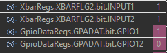
    The point is when I look into debugger I see this at startup when PWM is turned OFF (both outputs are in logical 0):

    However when I turn on PWM then I see that PWM pins are alternating:


    But Xbar INPUT1 and INPUT2 are always logical 1. It is not changing. It is like latched state in logical 1.

    TripZone is never activated. 

    Can you advise, plase?

  • If you are looking at the XBAR flags, they get latched. You have to clear them after they latch.

    Nima

  • Well, the clearing Xbar flags is one part of the problem. I cannot clear them every PWM pulse that is too many interrupts. So it makes possible only OST tripzone, not CBC due to frequent clearing...

    On the other hand PWM output was not latched anyway. Can you see any mistake in my configuration?

  • The flag is the only part that is latched... The signal itself is not latched. It goes foolows the input signal.

  • Thanks for the explanation of Xbar flags.

    The tripzone was not activated at all. Do you see any obvious mistake in the source code that I sent before?

  • Juraj Koys said:

    GPIO_setPadConfig(1,   GPIO_PIN_TYPE_STD);
    GPIO_setPadConfig(12, GPIO_PIN_TYPE_INVERT);

    XBAR_setInputPin(XBAR_INPUT1,  1U);
    XBAR_setInputPin(XBAR_INPUT2, 12U);

        EPWM_enableDigitalCompareTripCombinationInput(EPWM7_BASE, EPWM_DC_COMBINATIONAL_TRIPIN1, EPWM_DC_TYPE_DCAL);
        //EPWM_enableDigitalCompareTripCombinationInput(EPWM7_BASE, EPWM_DC_COMBINATIONAL_TRIPIN3, EPWM_DC_TYPE_DCBL);
        EPWM_enableDigitalCompareTripCombinationInput(EPWM7_BASE, EPWM_DC_COMBINATIONAL_TRIPIN2, EPWM_DC_TYPE_DCAH);
        //EPWM_enableDigitalCompareTripCombinationInput(EPWM7_BASE, EPWM_DC_COMBINATIONAL_TRIPIN6, EPWM_DC_TYPE_DCBH);
        EPWM_setTripZoneDigitalCompareEventCondition(EPWM7_BASE, EPWM_TZ_DC_OUTPUT_A2, EPWM_TZ_EVENT_DCXL_HIGH_DCXH_LOW);
        //EPWM_setTripZoneDigitalCompareEventCondition(EPWM7_BASE, EPWM_TZ_DC_OUTPUT_B2, EPWM_TZ_EVENT_DCXL_LOW);
        EPWM_setDigitalCompareEventSource(EPWM7_BASE, EPWM_DC_MODULE_A, EPWM_DC_EVENT_2, EPWM_DC_EVENT_SOURCE_ORIG_SIGNAL);
        //EPWM_setDigitalCompareEventSource(EPWM7_BASE, EPWM_DC_MODULE_B, EPWM_DC_EVENT_2, EPWM_DC_EVENT_SOURCE_ORIG_SIGNAL);
        EPWM_setDigitalCompareEventSyncMode(EPWM7_BASE, EPWM_DC_MODULE_A, EPWM_DC_EVENT_2, EPWM_DC_EVENT_INPUT_NOT_SYNCED);
        //EPWM_setDigitalCompareEventSyncMode(EPWM7_BASE, EPWM_DC_MODULE_B, EPWM_DC_EVENT_2, EPWM_DC_EVENT_INPUT_NOT_SYNCED);
        EPWM_setTripZoneAction(EPWM7_BASE, EPWM_TZ_ACTION_EVENT_TZA, EPWM_TZ_ACTION_LOW);  // Configure ePWMxA to output LOW on TZB TRIP
        //EPWM_setTripZoneAction(ulEPWM_base, EPWM_TZ_ACTION_EVENT_TZB, EPWM_TZ_ACTION_LOW);  // Configure ePWMxB to output LOW on TZB TRIP
        EPWM_disableDigitalCompareSyncEvent(EPWM7_BASE, EPWM_DC_MODULE_A);
        //EPWM_disableDigitalCompareSyncEvent(EPWM7_BASE, EPWM_DC_MODULE_B);
        EPWM_disableDigitalCompareBlankingWindow(EPWM7_BASE);
        EPWM_disableDigitalCompareWindowInverseMode(EPWM7_BASE);
        EPWM_selectCycleByCycleTripZoneClearEvent(EPWM7_BASE, EPWM_TZ_CBC_PULSE_CLR_CNTR_ZERO);
        EPWM_enableTripZoneSignals(EPWM7_BASE, EPWM_TZ_SIGNAL_DCAEVT2 /*| EPWM_TZ_SIGNAL_DCBEVT2*/);

    Is this your EPWM trip zone code?

  • So you have DCAEVT2 and DCBEVT2 setup to use the TRIPIN1/2 and TRIPIN3/6. Then you have the TZA action to clear the EPWM LOW and TZB action to clear the EPWM low.

    The TZA and TZB signals come from the ORED OST and CBC circuit.

    Then you have DCAEVT2 enabled in CBC sources. You have set CBC to latch to clear on CTR=ZERO.

    With this setup, when TRIPIN2 is LOW and TRIPIN1 is HIGH, you will trun off your EPWM.

    You have TRIPIN1 as GPIO1.

    TRIPIN2 as inverted GPIO12.

    That is the configuration you have and I dont see a mistake.

  • Thank you. I have finally managed to make it work :-) So my issue is resolved.

    However there is a certain disadvantage when using this solution.

    If I configure tripzone only for an overvoltage protection I simply use EPWM_TZ_EVENT_DCXL_HIGH so that whenever the overvoltage comparator detects overvoltage immediatelly the tripzone is activated. The DC condition DCXL_HIGH is satisfied immediatelly.

    Lets suppose I want to protect device from overvoltage and also from short-circuit at H-bridge as mentioned above.

    I have to configure EPWM_TZ_EVENT_DCXL_HIGH_DCXH_LOW therefore whenever the overvoltage comparator detects overvoltage the tripzone is activated only when DCXH_LOW. It means that we may wait several microseconds for PWM1A to change its state.


    Is it correct? Or am I wrong?

  • You know this EPWM_TZ_EVENT_DCXL_HIGH_DCXH_LOW means, DCAL is HIGH AND DCAH is LOW AT THE SAME TIME before this triggers?

  • the two conditions DCXL  HIGH and DCXH LOW are ANDED together. They must both be active.

    Nima