Hi,
Using Custom Board TMS320F28375S , Working with f28375S example SCI Loop back interrupt code but i couldn't communicate it .Previously i had used LauncpadXl-F28379D for that i have used for SCI Communication "_LAUNCHXL_F28379D" As a predefined symbol.
So , I have tried with "_LAUNCHXL_F28375S " &"_LAUNCHXL_F28377S" as predefined symbol , but its not works ...
Is there any configuration methods for SCI -Communication in TMS320F28375S controller ?
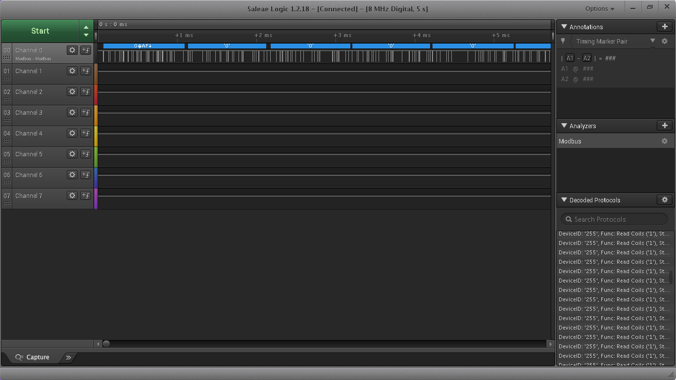
when i have checked with transmit pin in logic analyzer, its show always high ..

The code below i have Checked :
//
// Included Files
//
#include "driverlib.h"
#include "device.h"
//
// Defines
//
// Define AUTOBAUD to use the autobaud lock feature
//#define AUTOBAUD
//
// Globals
//
uint16_t loopCounter = 0;
//
// Main
//
void main(void)
{
uint16_t receivedChar;
unsigned char *msg;
uint16_t rxStatus = 0U;
//
// Configure PLL, disable WD, enable peripheral clocks.
//
Device_init();
//
// Disable pin locks and enable internal pullups.
//
Device_initGPIO();
//
// Configuration for the SCI Rx pin.
//
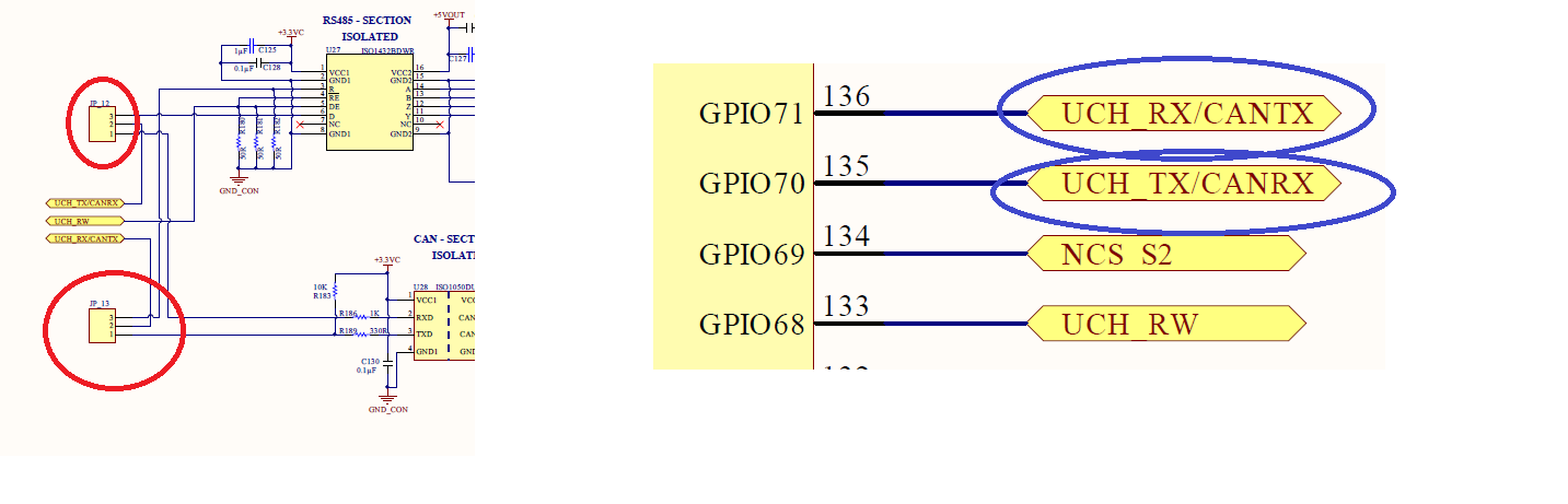
GPIO_setMasterCore(71, GPIO_CORE_CPU1);
GPIO_setPinConfig(DEVICE_GPIO_CFG_SCIRXDA);
GPIO_setDirectionMode(71, GPIO_DIR_MODE_IN);
GPIO_setPadConfig(71, GPIO_PIN_TYPE_STD);
GPIO_setQualificationMode(71, GPIO_QUAL_ASYNC);
//
// Configuration for the SCI Tx pin.
//
GPIO_setMasterCore(70, GPIO_CORE_CPU1);
GPIO_setPinConfig(DEVICE_GPIO_CFG_SCITXDA);
GPIO_setDirectionMode(70, GPIO_DIR_MODE_OUT);
GPIO_setPadConfig(70, GPIO_PIN_TYPE_STD);
GPIO_setQualificationMode(70, GPIO_QUAL_ASYNC);
//
// Initialize interrupt controller and vector table.
//
Interrupt_initModule();
Interrupt_initVectorTable();
//
// Initialize SCIA and its FIFO.
//
SCI_performSoftwareReset(SCIB_BASE);
//
// Configure SCIA for echoback.
//
SCI_setConfig(SCIB_BASE, DEVICE_LSPCLK_FREQ, 9600, (SCI_CONFIG_WLEN_8 |
SCI_CONFIG_STOP_ONE |
SCI_CONFIG_PAR_NONE));
SCI_resetChannels(SCIB_BASE);
SCI_resetRxFIFO(SCIB_BASE);
SCI_resetTxFIFO(SCIB_BASE);
SCI_clearInterruptStatus(SCIB_BASE, SCI_INT_TXFF | SCI_INT_RXFF);
SCI_enableFIFO(SCIB_BASE);
SCI_enableModule(SCIB_BASE);
SCI_performSoftwareReset(SCIB_BASE);
#ifdef AUTOBAUD
//
// Perform an autobaud lock.
// SCI expects an 'a' or 'A' to lock the baud rate.
//
SCI_lockAutobaud(SCIB_BASE);
#endif
//
// Send starting message.
//
msg = "\r\n\n\nHello World!\0";
SCI_writeCharArray(SCIB_BASE, (uint16_t*)msg, 17);
msg = "\r\nYou will enter a character, and the DSP will echo it back!\n\0";
SCI_writeCharArray(SCIB_BASE, (uint16_t*)msg, 62);
for(;;)
{
msg = "\r\nEnter a character: \0";
SCI_writeCharArray(SCIB_BASE, (uint16_t*)msg, 22);
//
// Read a character from the FIFO.
//
receivedChar = SCI_readCharBlockingFIFO(SCIB_BASE);
rxStatus = SCI_getRxStatus(SCIB_BASE);
if((rxStatus & SCI_RXSTATUS_ERROR) != 0)
{
//
//If Execution stops here there is some error
//Analyze SCI_getRxStatus() API return value
//
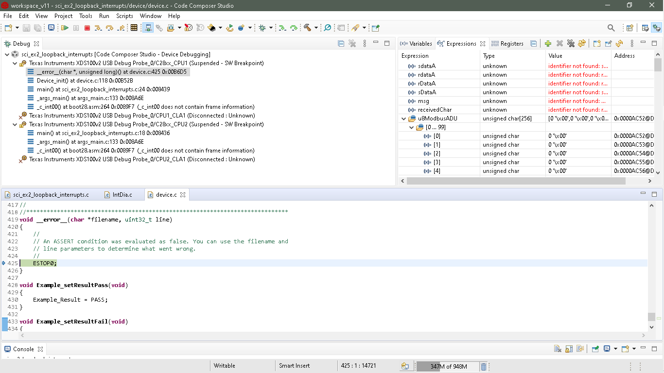
ESTOP0;
}
//
// Echo back the character.
//
msg = " You sent: \0";
SCI_writeCharArray(SCIB_BASE, (uint16_t*)msg, 13);
SCI_writeCharBlockingFIFO(SCIB_BASE, receivedChar);
//
// Increment the loop count variable.
//
}
}
//
// End of File
//
Thanks & Regards,
Rani