This thread has been locked.

If you have a related question, please click the "Ask a related question" button in the top right corner. The newly created question will be automatically linked to this question.

TMS320F280049: Timing delay to restart the PWM signal when force disabled with AQCSFRC register

Part Number: TMS320F280049
Other Parts Discussed in Thread: TMS320F28069,

Hi Team, 

We have requirement to generate fixed number of PWM cycles periodically. 

Requirement : 

We need to start the PWM signal in the ECAP1 interrupt and count the number cycles with DMA by writing to PWM registers on every period overflow and generate the DMA interrupt at the end of transfer (93 cycles) and in the DMA ISR disable the PWM and repeat it on the next ECAP interrupt. 

Implementation : 

PWM_Initialization
{
	....
	....
	//Forced to low 
	EPwm2Regs.AQCSFRC.bit.CSFA = 0x01;
	EPwm2Regs.AQCSFRC.bit.CSFB = 0x01;
	....
	....
}

ECAP1_ISR {
	.....
	.....
	//Forcing is disabled
	EPwm2Regs.AQCSFRC.bit.CSFA = 0x03;
        EPwm2Regs.AQCSFRC.bit.CSFB = 0x03;
	....
	....
}

DMA_INT //This is served after 93 cycles of PWM
{
	.....
	.....
	//Again forced to low
	EPwm2Regs.AQCSFRC.bit.CSFA = 0x01;
        EPwm2Regs.AQCSFRC.bit.CSFB = 0x01;
	....
}

We are observing delay in the start of the PWM and delay in stopping the PWM signal? I have posted the picture of delay at the start. 

** In the picture, PWM2 and PWM3 are forced to low and PWM4 is not, PWM2 -> PWM3 -> PWM4 are synchronized. 

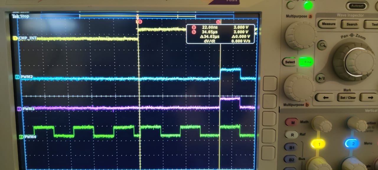
Please suggest a way to remove this 2 cycles delay at the start and end. 

Thanks, 

Ajay 

  • Hi Team, 

    We are working on the TMS320F28069 not TMS320F280049

    Thanks, 

    Ajay 

  • Hi Ajay,

    What other ePWM sub-modules are you configuring? 

    Have you tried to use the Trip Zone submodule instead of AQCSFRC?

    Best Regards,

    Marlyn

  • Hi Marlyn, 

    I am configuring Time-Base, counter-compare, Action qualifier and Event trigger submodules. Please check the below PWM init function. 

    void EPwm2_Init(void)
    {
        EPwm2Regs.TBPRD = 387;                      
        EPwm2Regs.TBPHS.half.TBPHS= 0x0000;          
        EPwm2Regs.TBCTR = 0x0000;
    
        // Set-up TBCTL
        EPwm2Regs.TBCTL.bit.CTRMODE = TB_COUNT_UPDOWN;        // Counter Up and Down mode
        EPwm2Regs.TBCTL.bit.PHSEN = TB_ENABLE;
        EPwm2Regs.TBCTL.bit.HSPCLKDIV = 0x00;
        EPwm2Regs.TBCTL.bit.CLKDIV = 0x01;
        EPwm2Regs.TBCTL.bit.PRDLD = TB_IMMEDIATE;//0x00;
        EPwm2Regs.TBCTL.bit.SYNCOSEL = TB_CTR_ZERO;
    
        //Compare values are written from DMA
        EPwm2Regs.CMPA.half.CMPA = 311;
        EPwm2Regs.CMPB = 76;
    
        //Setup Actions for EPwm2A
        EPwm2Regs.AQCTLA.bit.ZRO = 0x02;
        EPwm2Regs.AQCTLA.bit.PRD = 0x01;    
    
        //Setup Actions for EPwm2B
        EPwm2Regs.AQCTLB.bit.ZRO = 0x02;    
        EPwm2Regs.AQCTLB.bit.CAU = 0x01;    
        EPwm2Regs.AQCTLB.bit.PRD = 0x02;    
        EPwm2Regs.AQCTLB.bit.CBD = 0x01;    
    	
        //TX burst is disabled in the initialization
        EPwm2Regs.AQCSFRC.bit.CSFA = 0x01;
        EPwm2Regs.AQCSFRC.bit.CSFB = 0x01;
    
        // Setup Event Trigger
        EPwm2Regs.ETSEL.bit.SOCASEL = 0x01;         // ADCSOCB on TBCTR=TBPRD
        EPwm2Regs.ETSEL.bit.SOCAEN = 1;             // Enable SOCA generation
        EPwm2Regs.ETPS.bit.SOCAPRD = 1;             // Generate SOCA on 1st event
    }

    I will explore the use of Tripzone submodule only if AQCSFRC is not useful here. Please let us know if the observed delay in expected? Is there a way to reduce this delay? 

    Thanks, 

    Ajay 

  • HI Team, 

    Tried to disable PWM signal with software forced Trip-zone results are as below. 

    Observed Half cycle (PWM cycle) delay in PWM restart. 


    In the ECAP ISR, We are synchronizing the PWM's, PWM2 -> PWM3-> PWM4, You can PWM4 is getting synchronized and restarted immediately(Which is not forcibly disabled). 

    The code with trip-zone is as below: 

    PWM_Initialization
    {
    	....
    	....
        //TripZone
        EALLOW;
    
        // What do we want any of the TZs to do?
        EPwm3Regs.TZCTL.bit.TZA = TZ_FORCE_LO;
        EPwm3Regs.TZCTL.bit.TZB = TZ_FORCE_LO;
    
        //Clear
        EPwm3Regs.TZCLR.all = 0x07;
    
        // Enable TZ interrupt on any TZ event
        EPwm3Regs.TZEINT.bit.OST = 0;
        EDIS;
    	....
    	....
    }
    
    ECAP1_ISR {
    	.....
    	.....
        //Tripzone
        EALLOW;
        EPwm2Regs.TZCLR.all = 0x07;
        EDIS;
    	....
    	....
    }
    
    DMA_INT //This is served after 93 cycles of PWM
    {
    	.....
    	.....
        //Tripzone
        EALLOW;
        EPwm2Regs.TZFRC.bit.OST = 0x01;
        EPwm3Regs.TZFRC.bit.OST = 0x01;
    
        EDIS;
    	....
    }

    Let us know how can we remove this half cycle delay in the restart of PWM's. 

    Thanks, 

    Ajay 

  • Ajay,

    it seems like there may be a few ways to solve this.

    AQ solution: I do not expect a two period delay due to AQCSFRC. This could possibly due to the length of your capture interrupt. To debug this I would recommend that you confirm CMP_INT toggle occurs immediately after the AQCSFRC is disabled, once we confirm this delay is as long as it looks like it is we can debug further if you care.

    TZ solution: it looks like you are getting pretty close to the answer here. Its possible that you are missing a compare event due to your sync scheme. Please note that the CMPx registers work on an "equal to" comparison, not an "equal to or greater than" comparison. Stated another way if you sync to a TBPHS value of 10 and your CMPA value=5 the CMPA event will be missed until the next cycle. Also please remember that if set your output high near the end of the last period it will not occur until the TBCTR wraps around and the PWM output will stay low.

    Another common fix is to change the counter direction on sync. I don't know exactly what you are trying to accomplish, but you can get the counters to count up or count down after a sync even with the TBPHS.PHSDIR bit.

    If you're still struggling with this I might suggest a new approach; This sounds a lot like something that might be easily solved by looking at our appnote on how to achieve 0% duty cycle. https://www.ti.com/lit/pdf/spraai1 Please note that this appnote is only partially applicable for F2806x. You could still use your slick DMA trick to control when the PWM is on or off, but update the CMPx and AQ force bits as described in the appnote.

    (App note supplement) On newer devices like F2806x( anything a Type 1,2,3, or 4 PWM) the shadow load occurs before CMPA is compared to TBCTR. This is closed with in the design and will always happen.

    How does the appnote affect newer devices like F2806x? For newer devices you only need to worry about Up-down count mode. As described before CMPA =0 will not be missed. However, when switching from a CMPA =0  to a non-zero CMPA the workaround is still suggested to be used.

    Regards,|
    Cody 

  • Hi Team, 

    Thanks for the suggestions. 

    AQ solution : Yes, in the ECAP ISR, right at the begging of the ISR we are toggling the CMP_INT and immediately disabling the AQCSFRC. I am observing some time One period delay and some time 2 periods delay. Please help to debug further. 

    __interrupt
    void ECap1_Isr(void)	// 0x000D70  ECAP1_INT (ECAP1)
    {
    	if (ECap1Regs.ECFLG.bit.CTR_EQ_PRD)
    	{
    		...
    		...
    	}
    	if (ECap1Regs.ECFLG.bit.CTR_EQ_CMP)
    	{
    		tmp_CMP++;
    	    DEBUG5_TOGGLE; //CMP_INT toggle 
    
            //Forced Sync for PWM2 and other PWM's will be synched with PWM2 as SYNCOUT -> SYNCIN
            EPwm2Regs.TBCTL.bit.SWFSYNC = 1; //Synchronization
    		
    		EPwm2Regs.AQCSFRC.bit.CSFA = 0x03;
    		EPwm2Regs.AQCSFRC.bit.CSFB = 0x03;
    
    		...
    		...
    	}
    	...
    	...
    }

    TZ solution: If the TBPHS.PHSDIR bit is set or cleared the results are same, I am observing half period delay. 

    May be this is expected because

    when TBCTR = 0, We want the EPWMA & EPWMB to set to High 

    EPwm2Regs.AQCTLA.bit.ZRO = 0x02;

    EPwm2Regs.AQCTLB.bit.ZRO = 0x02;

    But when the synch pulse is generated, Definitely TBPHS > 0 as its not taking the action defined at TBCTR = 0 till the next roll over and PWM signals are staying low. Please confirm is my understanding is right. 

    Is there any other solution you suggest to resolve this issue? My goal is restart the PWM signal very close to ECap1Regs.ECFLG.bit.CTR_EQ_CMP bit set and synchronize PWM2, PWM3, PWM4 and stop after fixed number of cycles count and repeat on next ECap1Regs.ECFLG.bit.CTR_EQ_CMP event. 

    Thanks, 

    Ajay 

  • Ajay, 

    1. AQ solution:
      1. does you EPWM CMPx event happen on or near TBCTR =0? That event will probably be missed with the way you have written the code. Please clear the AQCSFRC and then sync the PWMs afterwards. Does this change your results?
    2. TZ solution:
      1. Yes your understanding is correct.

    I think your solution is very close to being correct. There is some boundary condition at the start that isn't quite correctly accounted for, but i'm confident it can be corrected. Let me know what happens when you clear the forcing event before syncing the PWMs.

    Finally one other solution you could try is to use the non-continuous software force to force the PWM high during the first period, I believe this too could fix your situation.

    Regards,
    Cody 

  • Hi Team, 

    Please check my responses below: 

    AQ solution:

    1. Does you EPWM CMPx event happen on or near TBCTR =0?

    [Ajay] : Not necessarily, ECAP and PWM are asynchronous so it may happen at any time, Thats the reason we are synchronizing the PWM when the ECAP CMP event is triggered and restart the PWM signal. 

    2. Please clear the AQCSFRC and then sync the PWMs afterwards. Does this change your results?

    [Ajay] : Tried this and see the result below, Its same as before, No change in results. 

    3. Finally one other solution you could try is to use the non-continuous software force to force the PWM high during the first period. 

    [Ajay] : Tried this as well but does not resolve my issue. Its just increasing the width of the first half cycle towards ECAP CMP event but thats not the intension, We need to move the complete signal itself. Please check the result below: 


    Till now, I have observed good results with TZ, with a delay of around 8us (Half period), Please let me know if we can resolve it further. 

    Thanks, 

    AJAY 

  • Ajay,

    what is the CMPx value when you see the issue using the action qualifier? What is the value when you do not see the issue?

    Hmm, with the non-continuous software force solution i was attempting to see if a rising event was being missed for some reason, but if what you said is true, then it appears that the falling event is being missed as well.

    With the TZ solution what event are you expecting forcing the PWM output high? If its a CMPx event, what value is it set to? What event are you expecting to force the PWM low afterwards?

    Can you observe what is the value of the TBCTR after a sync pulse? Is it being correctly reset? Is it counting up or down?

    Regards,
    Cody

  • HI Team, 

    Questions are asked repeatedly without any resolution suggested, Its been discussed for long time now but seems you are still not understanding what I am trying to do here. 

    Can we have quick call on this to understand better? I will ask local TI team to arrange a call with you if possible. 

    Thanks, 

    Ajay 

  • Ajay,

    Due to inclement weather in our region, many of our subject matter experts(both Cody and Marlyn) are without power and unable to provide support at this time.  An expert will get back to you as soon as possible but it likely will not be until next week.

    Best,

    Matthew

  • Ajay,

    unfortunately there is a lot of configurability in the PWM module and therefore there could be a lot of issues causing a delay like this. So, yes sometimes a lot of questions need to be asked, sorry for the inconvenience. If you feel I am asking the same questions over again feel free to bring those up, either I have indeed asked duplicate questions(totally possible, or there is some idiosyncrasy that I have not conveyed very well in my questions.

    Problem statement: I believe you are trying to restart the PWM after an event. This event is detected by the eCAP module. After said event you want the PWM to start from zero immediately and begin to output a PWM signal for "X" periods and you have chosen to use the DMA to turn it off the PWM output after "X" number of periods.

    If my understanding of what you are trying to do is not correct please feel free to correct it.

    Now thinking further on the AQ solution: There are a couple of bits "AQSFCR.RLDCSF" which control when the AQCSFRC register is loaded. This can be at period, zero, both or immediately. Being that your issue is synchronized to a periodic event, I think this is something you should investigate. What value are you using for RLDCSF? Does the behavior change when you change it to load on both TBCTR=0 and TBCTR=PRD, what about if you use immediate load mode?

    Being that you see at least a 1/2 period delay in both solutions this may suggest that you have something wrong with the synchronization that occurs wither or not you are using AQ or the TZ to force the PWM value. This is why I had asked you to verify if the TBCTR is being reset when and how you were expecting. Can you please confirm this is being reset immediately after the eCAP interrupt? 

    Additionally, as Matt has indicated, we are experiencing power outages which is slowing down responses and preventing us from running any tests. 

    Regards,
    Cody 

  • Hi Cody, 

    The Problem statement Is Correct! 

    AQ Solution : I have already explored the bit "AQSFCR.RLDCSF" there is not much difference with delay, If I load it immediately i.e., set AQSFCR.RLDCSF = 3 then the pulse width is getting increased but not recovered the lost cycles. 

    Regarding the synchronization : Upon synchronization the TBCTR is being loaded properly with the phase difference but I have set PHSDIR = 1 and observed sometimes TBCTR counts up and sometimes counts down, I am expecting it to counts up after sync as PHSDIR = 1. 

    TZ solution : I am able to achieve as less as1.3us delay from ECAP event, Corrected the function to function calls to clear the TZ. 

    May be we will go with TZ solution, Please suggest if I am missing anything on TZ solution to improve. I will be clearing the TZ and generate PWM only based on some conditions so need to call other functions and make decision but its adding up the delay and missing the first event at TBCTR =0 and adding to the first half cycle delay. Please suggest a way to handle with minimum delay. 

    Thanks, 

    Ajay 

  • Ajay,

    Ajay Kumar3 said:
    AQ Solution : I have already explored the bit "AQSFCR.RLDCSF" there is not much difference with delay, If I load it immediately i.e., set AQSFCR.RLDCSF = 3 then the pulse width is getting increased but not recovered the lost cycles. 

    This behavior above sounds like changing to immediate mode is allowing the rising event  to happen during the first PWM cycle, but the falling event is still being missed. Are you changing the falling event's value at all?  Is there a chance that during the first cycle the falling event is out of range? As soon as the CSFx is de-asserted the other circuits should continue as if the CSFx event didn't happen. This is very well tested and known to work.

    Ajay Kumar3 said:
    Regarding the synchronization : Upon synchronization the TBCTR is being loaded properly with the phase difference but I have set PHSDIR = 1 and observed sometimes TBCTR counts up and sometimes counts down, I am expecting it to counts up after sync as PHSDIR = 1. 

    Ajay, this behavior is very unexpected. The PHSDIR is known to be reliable, so I would suspect something in your code is changing this value, or the behavior we are seeing is being misunderstood. 

    Related to a comment you have a few posts back about how the behavior of the AQ solution was not deterministic and that after you remove the continuous force sometimes there is a high pulse, sometimes there is not. I believe this is because you have interrupted the previous cycle while it was outputting high or low, and that the first event you expect to be driving the output high is being missed. My initial expectation is that this is due to skipping over a CMPx, TBCTR=0, or TBCTR= Period event.

    As for the trip-zone delay you are seeing that it is taking ~100 instruction cycles before the TZ clears it. being that this is SW based this sounds about reasonable, perhaps maybe a little high. Depending on your system this delay can be accounted for by adjusting the TBPHS registers to advance the first PWM cycle x number of cycles. This will likely cause your first pulse to be shortened, but should best align your PWM period to the eCAP event. So you would need to choose what is best for your system.

    Regards,
    Cody 

  • Hi Cody, 

    Thanks! For now I will go with the TZ solution, If there are any issues later will get back to you. Thanks for your support. 

    Thanks, 

    Ajay