Part Number: TMDSCNCD28379D
Other Parts Discussed in Thread: AMIC110
Hi,
I'm new with EtherCAT protocol, and I try communication between a F28379D control board and a Beckhoff piggyback.
I have many questions :
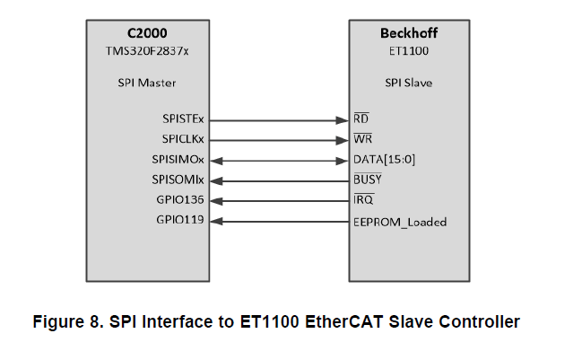
- First one is a hardware question :

Is this mandatory to connect /IRQ and EEPROM_Loaded from the ET1100 ? I've read on Piggyback datasheet that it wasn't mandatory..
If yes, on which GPIO have I to connect these 2 signals ?
Currently, these signals are available on TMDSCNCD28379D, but I'll use later a TMS320F28379D in PTP package, so GPIO119 & GPIO136 won't be available.
- Software question :
I've follow SPRUIF9 app notes to execute a simple EtherCAT communication.
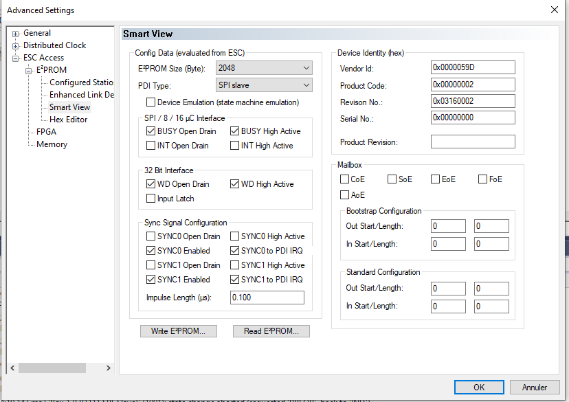
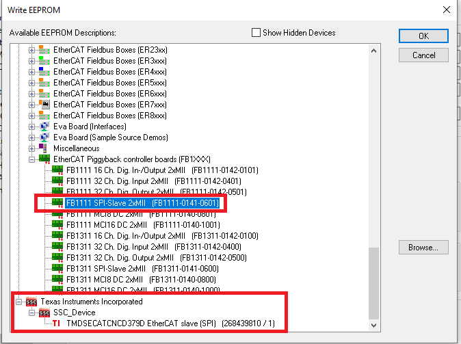
- TwinCAT found the piggyback ; I can write on the EEPROM, but which binary file have I to write ?
- The piggyback binary file for SPI (FB1111 SPI-Slave 2xMII (FB1111-0141-0601))
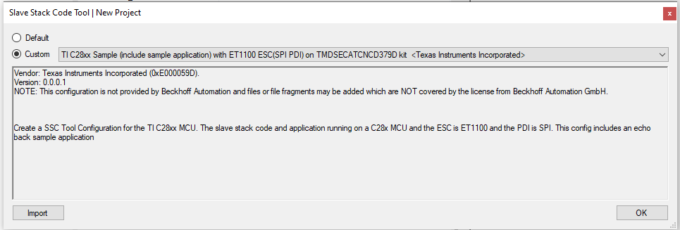
- Or I have to create a binary file linked to the F28379D with the SSC Tool ? (in the picture below, I've created a binary file for the TMDSECATCNCD379D, but I don't use this board, it was just to try)
On TwinCAT, I'm INIT mode. But I've read on other topics it was ok, because I am not running an EtherCAT slave stack on the MCU yet, is that right ?

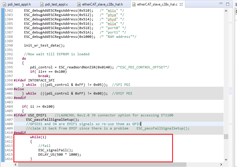
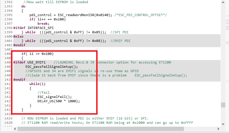
When I execute pdi_hal_test_app on CCS, nothing happens :
- Do I need to connect also SYNC0 and SYNC1 ?
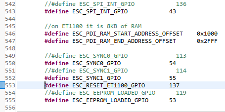
In etherCAT_slave_c28x_hal.h, I've found :
        #define ESC_SPI_INT_GPIO            136

        //on ET1100 it is 8KB of RAM
        #define ESC_PDI_RAM_START_ADDRESS_OFFSET    0x1000
        #define ESC_PDI_RAM_END_ADDRESS_OFFSET      0x2FFF

        #define ESC_SYNC0_GPIO              113
        #define ESC_SYNC1_GPIO              114
        #define ESC_RESET_ET1100_GPIO       137
        #define ESC_EEPROM_LOADED_GPIO      119
I need to modify these line ?
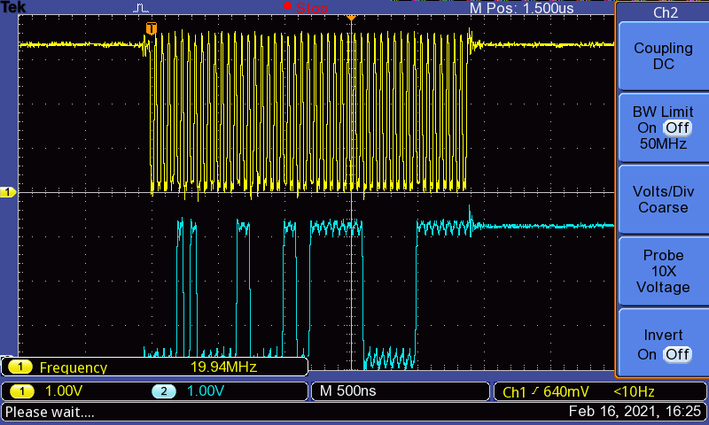
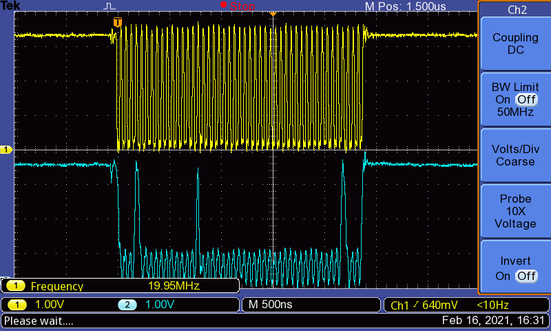
I had a look with the oscilloscope, I have no SPI signals.
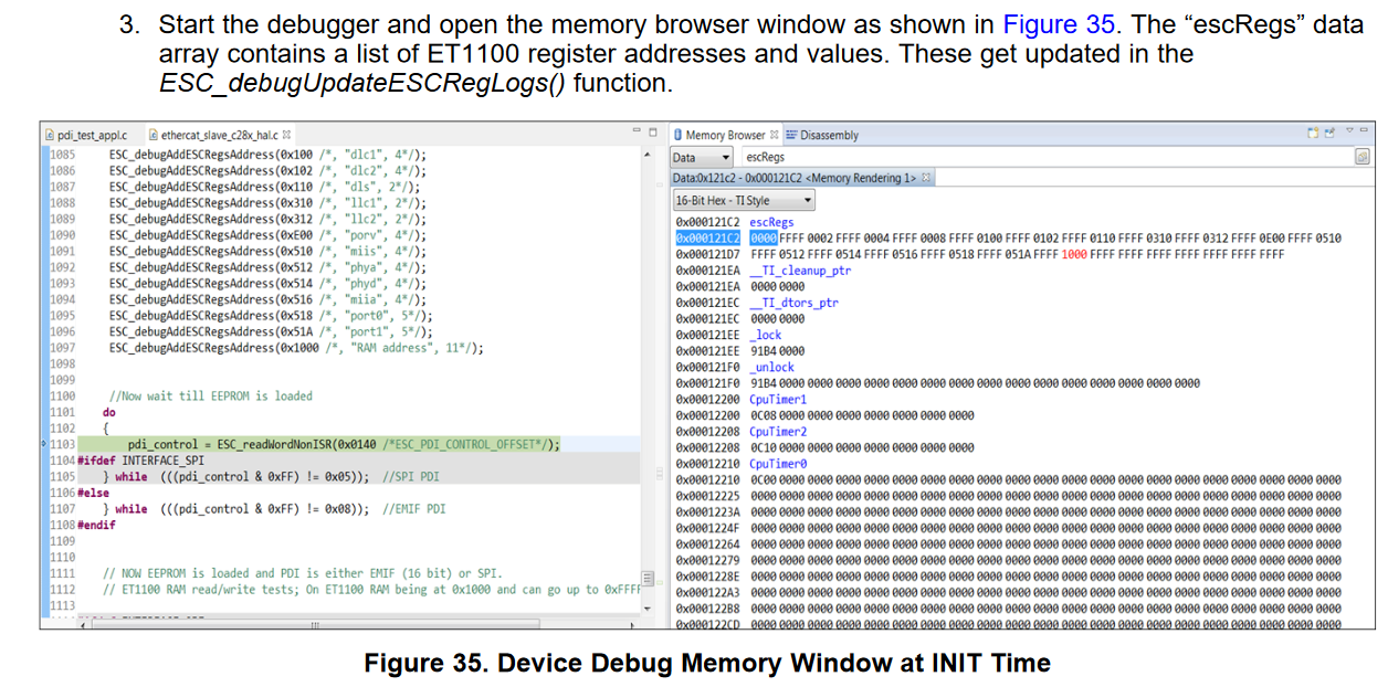
When I want to read value in the memory browser, I cannot find "escRegs" ; what's the address ?
Thank you, regards.
EDIT :
I've made some modifications :
- I've connected EEPROMLOADED signal to GPIO53
- I've connected SPI_INTsignal to GPIO43
In etherCAT_slave_c28x_hal.h, I've modified :
//#define ESC_SPI_INT_GPIO            136
#define ESC_SPI_INT_GPIO            43

//on ET1100 it is 8KB of RAM
#define ESC_PDI_RAM_START_ADDRESS_OFFSET    0x1000
#define ESC_PDI_RAM_END_ADDRESS_OFFSET      0x2FFF

#define ESC_SYNC0_GPIO              113
#define ESC_SYNC1_GPIO              114
#define ESC_RESET_ET1100_GPIO       137

//#define ESC_EEPROM_LOADED_GPIO      119
#define ESC_EEPROM_LOADED_GPIO      53
But nothing has changed, I've still haven't SPI signals on oscilloscope, and I can't find "escRegs" on the memory Browser ; what is it address ?
Thank you,
Regards