This thread has been locked.

If you have a related question, please click the "Ask a related question" button in the top right corner. The newly created question will be automatically linked to this question.

CCS/TMDSHVMTRINSPIN: Motor identification lab05

Part Number: TMDSHVMTRINSPIN
Other Parts Discussed in Thread: C2000WARE,

Tool/software: Code Composer Studio

Hello team,

We are using   TMDSHVMTRINSPIN development kit, TMS320F280049C control card  and TMDSADAP180TO100, by loading the example projects presented in below path "C:\ti\c2000\C2000Ware_MotorControl_SDK_3_00_01_00\solutions\tmdshvmtrinspin\f28004x\ccs\sensorless_foc \is05_". we follow the user guide presented in C:\ti\c2000\C2000Ware_MotorControl_SDK_3_00_01_00\solutions\common\sensorless_foc\docs\labs" , we flash  lab05, in the watch window we set motorVars.flagEnableSys=1 and motorVars.flagRunIdentAndOnLine=1 ,as per the guide flagRunIdentAndOnLine become zero and  motorVars.flagMotorIdentified becomes 1 ,but we didn't get like this, in my watch window motorVars.flagRunIdentAndOnLine is shows always one.

1.can you please help me to resolve this issue?

watch window always have the sate is online only:

thank you

  • What PWM and control frequency are you using?

    Does the ISR enter successfully?

  • Hi thanks for the reply, we are using pwm with 15KHz,yes sir it entered into main ISR.

    1.We flash the lab03 and lab04, my motor spin well.

    2. we flash the lab05, in motor identification process motor  completes one rotation, but after that my motor getting oscillations,

    3. we did some changes in  code ,we changed GPIO  pins and ADC pins, we changed hal.c and hal.h files (we shown them in below).,can you help me to resolve this?

    //#############################################################################
    // $TI Release: MotorControl SDK v3.00.01.00 $
    // $Release Date: Tue May 26 19:13:59 CDT 2020 $
    // $Copyright:
    // Copyright (C) 2017-2018 Texas Instruments Incorporated - http://www.ti.com/
    //
    // Redistribution and use in source and binary forms, with or without
    // modification, are permitted provided that the following conditions
    // are met:
    // 
    //   Redistributions of source code must retain the above copyright
    //   notice, this list of conditions and the following disclaimer.
    // 
    //   Redistributions in binary form must reproduce the above copyright
    //   notice, this list of conditions and the following disclaimer in the
    //   documentation and/or other materials provided with the
    //   distribution.
    // 
    //   Neither the name of Texas Instruments Incorporated nor the names of
    //   its contributors may be used to endorse or promote products derived
    //   from this software without specific prior written permission.
    // 
    // THIS SOFTWARE IS PROVIDED BY THE COPYRIGHT HOLDERS AND CONTRIBUTORS
    // "AS IS" AND ANY EXPRESS OR IMPLIED WARRANTIES, INCLUDING, BUT NOT
    // LIMITED TO, THE IMPLIED WARRANTIES OF MERCHANTABILITY AND FITNESS FOR
    // A PARTICULAR PURPOSE ARE DISCLAIMED. IN NO EVENT SHALL THE COPYRIGHT
    // OWNER OR CONTRIBUTORS BE LIABLE FOR ANY DIRECT, INDIRECT, INCIDENTAL,
    // SPECIAL, EXEMPLARY, OR CONSEQUENTIAL DAMAGES (INCLUDING, BUT NOT
    // LIMITED TO, PROCUREMENT OF SUBSTITUTE GOODS OR SERVICES; LOSS OF USE,
    // DATA, OR PROFITS; OR BUSINESS INTERRUPTION) HOWEVER CAUSED AND ON ANY
    // THEORY OF LIABILITY, WHETHER IN CONTRACT, STRICT LIABILITY, OR TORT
    // (INCLUDING NEGLIGENCE OR OTHERWISE) ARISING IN ANY WAY OUT OF THE USE
    // OF THIS SOFTWARE, EVEN IF ADVISED OF THE POSSIBILITY OF SUCH DAMAGE.
    // $
    //#############################################################################
    
    //! \file   solutions/tmdshvmtrinspin/f28004x/drivers/hal.c
    //! \brief  Contains the various functions related to the HAL object
    //!
    
    
    // **************************************************************************
    // the includes
    
    // drivers
    
    // modules
    #include "user.h"
    
    // platforms
    #include "hal.h"
    #include "hal_obj.h"
    
    // libraries
    #include "datalog.h"
    
    #ifdef _FLASH
    #pragma CODE_SECTION(Flash_initModule, ".TI.ramfunc");
    #endif
    
    // **************************************************************************
    // the defines
    
    
    // **************************************************************************
    // the globals
    
    
    // **************************************************************************
    // the functions
    void HAL_cal(HAL_Handle handle)
    {
    
      return;
    } // end of HAL_cal() function
    
    void HAL_disableGlobalInts(HAL_Handle handle)
    {
    
      // disable global interrupts
      Interrupt_disableMaster();
    
      return;
    } // end of HAL_disableGlobalInts() function
    
    void HAL_disableWdog(HAL_Handle halHandle)
    {
    
      // disable watchdog
      SysCtl_disableWatchdog();
    
      return;
    } // end of HAL_disableWdog() function
    
    void HAL_enableADCInts(HAL_Handle handle)
    {
        HAL_Obj *obj = (HAL_Obj *)handle;
    
        // enable the PIE interrupts associated with the ADC interrupts
        Interrupt_enable(INT_ADCB1);        //C1
    
        // enable the ADC interrupts
        ADC_enableInterrupt(obj->adcHandle[1], ADC_INT_NUMBER1);
    
        // enable the cpu interrupt for ADC interrupts
        Interrupt_enableInCPU(INTERRUPT_CPU_INT1);
    
    #ifdef _VSF_EN_
        // enable the cpu timer 0 interrupt for FAST estimator
        Interrupt_enable(INT_TIMER0);
    #endif  // _VSF_EN_
    
        return;
    } // end of HAL_enableADCInts() function
    
    void HAL_enableADCIntsToTriggerCLA(HAL_Handle handle)
    {
        HAL_Obj *obj = (HAL_Obj *)handle;
    
        // enable the ADC interrupts
        // RC2/C1
        ADC_enableInterrupt(obj->adcHandle[1], ADC_INT_NUMBER1);
    
        return;
    } // end of HAL_enableADCIntsToTriggerCLA() function
    
    
    void HAL_enableDebugInt(HAL_Handle handle)
    {
    
        // enable debug events
        ERTM;
    
        return;
    } // end of HAL_enableDebugInt() function
    
    void HAL_enableGlobalInts(HAL_Handle handle)
    {
    
        // enable global interrupts
        Interrupt_enableMaster();
    
        return;
    } // end of HAL_enableGlobalInts() function
    
    
    HAL_Handle HAL_init(void *pMemory,const size_t numBytes)
    {
      HAL_Handle handle;
      HAL_Obj *obj;
    
      if(numBytes < sizeof(HAL_Obj))
        return((HAL_Handle)NULL);
    
      // assign the handle
      handle = (HAL_Handle)pMemory;
    
      // assign the object
      obj = (HAL_Obj *)handle;
    
      // disable watchdog
      SysCtl_disableWatchdog();
    
      // initialize the ADC handles
      obj->adcHandle[0] = ADCA_BASE;
      obj->adcHandle[1] = ADCB_BASE;
      obj->adcHandle[2] = ADCC_BASE;
    
      // initialize the ADC results
      obj->adcResult[0] = ADCARESULT_BASE;
      obj->adcResult[1] = ADCBRESULT_BASE;
      obj->adcResult[2] = ADCCRESULT_BASE;
    
      // initialize CLA handle
      obj->claHandle = CLA1_BASE;
    
      // initialize SCI handle
      obj->sciHandle[0] = SCIA_BASE;        //!< the SCIA handle
      obj->sciHandle[1] = SCIB_BASE;        //!< the SCIB handle
    
      // initialize SPI handle
      obj->spiHandle[0] = SPIA_BASE;        //!< the SPIA handle
      obj->spiHandle[1] = SPIB_BASE;        //!< the SPIB handle
    
      // initialize DMA handle
      obj->dmaHandle = DMA_BASE;            //!< the DMA handle
    
      // initialize DMA channel handle
      obj->dmaChHandle[0] = DMA_CH1_BASE;   //!< the DMA Channel handle
      obj->dmaChHandle[1] = DMA_CH2_BASE;   //!< the DMA Channel handle
      obj->dmaChHandle[2] = DMA_CH3_BASE;   //!< the DMA Channel handle
      obj->dmaChHandle[3] = DMA_CH4_BASE;   //!< the DMA Channel handle
    
      // initialize PWM handles for Motor 1
      obj->pwmHandle[0] = EPWM4_BASE;
      obj->pwmHandle[1] = EPWM5_BASE;
      obj->pwmHandle[2] = EPWM6_BASE;
    
      // initialize PGA handle
      obj->pgaHandle[0] = PGA1_BASE;        //!< the PGA handle
      obj->pgaHandle[1] = PGA3_BASE;        //!< the PGA handle
      obj->pgaHandle[2] = PGA5_BASE;        //!< the PGA handle
    
      // initialize CMPSS handle
      obj->cmpssHandle[0] = CMPSS1_BASE;    //!< the CMPSS handle
      obj->cmpssHandle[1] = CMPSS3_BASE;    //!< the CMPSS handle
      obj->cmpssHandle[2] = CMPSS5_BASE;    //!< the CMPSS handle
    
      // initialize DAC handle
      obj->dacHandle[0] = DACA_BASE;        //!< the DAC handle
      obj->dacHandle[1] = DACB_BASE;        //!< the DAC handle
    
      // initialize timer handles
      obj->timerHandle[0] = CPUTIMER0_BASE;
      obj->timerHandle[1] = CPUTIMER1_BASE;
      obj->timerHandle[2] = CPUTIMER2_BASE;
    
      // initialize pwmdac handles
      obj->pwmDACHandle[0] = EPWM8_BASE;        //GPIO14
      obj->pwmDACHandle[1] = EPWM8_BASE;        //GPIO15
      obj->pwmDACHandle[2] = EPWM1_BASE;        //GPIO18(N/A)
      obj->pwmDACHandle[3] = EPWM1_BASE;        //GPIO10
    
    #ifdef _EQEP_EN_
      // initialize QEP driver
      obj->qepHandle[0] = EQEP1_BASE;           // EQEP1
    //  obj->qepHandle[1] = EQEP2_BASE;         // EQEP2
    #endif
    
      return(handle);
    } // end of HAL_init() function
    
    
    void HAL_setParams(HAL_Handle handle)
    {
      HAL_setNumCurrentSensors(handle,USER_NUM_CURRENT_SENSORS);
      HAL_setNumVoltageSensors(handle,USER_NUM_VOLTAGE_SENSORS);
    
      // disable global interrupts
      Interrupt_disableMaster();
    
      // Disable the watchdog
      SysCtl_disableWatchdog();
    
    #ifdef _FLASH
      //
      // Copy time critical code and flash setup code to RAM. This includes the
      // following functions: InitFlash();
      //
      // The RamfuncsLoadStart, RamfuncsLoadSize, and RamfuncsRunStart symbols
      // are created by the linker. Refer to the device .cmd file.
      //
      memcpy(&RamfuncsRunStart, &RamfuncsLoadStart, (size_t)&RamfuncsLoadSize);
    #endif
    
      // Disable DC-DC controller
      ASysCtl_disableDCDC();
    
      // Enable temperature sensor
      ASysCtl_enableTemperatureSensor();
    
      // initialize the interrupt controller
      Interrupt_initModule();
    
      // init vector table
      Interrupt_initVectorTable();
    
      // Set up PLL control and clock dividers
      // PLLSYSCLK = 20MHz (XTAL_OSC) * 10 (IMULT) * 1 (FMULT) / 2 (PLLCLK_BY_2)
      SysCtl_setClock(SYSCTL_OSCSRC_XTAL |
                      SYSCTL_IMULT(10) |
                      SYSCTL_FMULT_NONE |
                      SYSCTL_SYSDIV(2) |
                      SYSCTL_PLL_ENABLE);
    
      // These asserts will check that the #defines for the clock rates in
      // device.h match the actual rates that have been configured. If they do
      // not match, check that the calculations of DEVICE_SYSCLK_FREQ and
      // DEVICE_LSPCLK_FREQ are accurate. Some examples will not perform as
      // expected if these are not correct.
      //
      ASSERT(SysCtl_getClock(DEVICE_OSCSRC_FREQ) == DEVICE_SYSCLK_FREQ);
      ASSERT(SysCtl_getLowSpeedClock(DEVICE_OSCSRC_FREQ) == DEVICE_LSPCLK_FREQ);
    
    
      // run the device calibration
      HAL_cal(handle);
    
      // setup the peripheral clocks
      HAL_setupPeripheralClks(handle);
    
    #ifdef CLA
      // setup CLA
      HAL_setupCLA(handle);
    #endif
    
      // setup the GPIOs
      HAL_setupGPIOs(handle);
    
    #ifdef _FLASH
      //
      // Call Flash Initialization to setup flash waitstates. This function must
      // reside in RAM.
      Flash_initModule(FLASH0CTRL_BASE, FLASH0ECC_BASE, DEVICE_FLASH_WAITSTATES);
    #endif
    
    #ifdef _PWMDAC_EN_
      // setup the PWM DACs
      HAL_setupPWMDACs(handle, USER_SYSTEM_FREQ_MHz);
    #endif
    
      // setup the ADCs
      HAL_setupADCs(handle);
    
      // setup the PGAs
      HAL_setupPGAs(handle);
    
      // setup the Dacs
      HAL_setupDACs(handle);
    
      // setup the CMPSSs
      HAL_setupCMPSSs(handle);
    
      // setup the PWMs
      HAL_setupPWMs(handle,
                    USER_SYSTEM_FREQ_MHz,
                    USER_PWM_PERIOD_usec,
                    USER_NUM_PWM_TICKS_PER_ISR_TICK);
    
      // set the current scale factor
      HAL_setCurrentScaleFactor(handle,USER_CURRENT_SF);
    
      // set the voltage scale factor
      HAL_setVoltageScaleFactor(handle,USER_VOLTAGE_SF);
    
      // setup the timers
      HAL_setupTimers(handle, USER_SYSTEM_FREQ_MHz);
    
      // setup the sci
      HAL_setupSCIA(handle);
    
      // setup the spiB for DRV8301_Kit_RevD
      HAL_setupSPIB(handle);
    
    #ifdef _EQEP_EN_
      // setup the eqep
      HAL_setupQEP(handle, HAL_QEP_QEP1);
    #endif
    
    #ifdef _VSF_EN_
      // setup the timer for estimator
      HAL_setupEstTimer(handle, USER_SYSTEM_FREQ_MHz, USER_EST_FREQ_Hz);
    #endif  // _VSF_EN_
    
      return;
    } // end of HAL_setParams() function
    
    
    void HAL_setupADCs(HAL_Handle handle)
    {
      HAL_Obj *obj = (HAL_Obj *)handle;
    
      SysCtl_delay(100U);
      ADC_setVREF(obj->adcHandle[2], ADC_REFERENCE_INTERNAL, ADC_REFERENCE_3_3V);
      ADC_setVREF(obj->adcHandle[1], ADC_REFERENCE_INTERNAL, ADC_REFERENCE_3_3V);
      ADC_setVREF(obj->adcHandle[0], ADC_REFERENCE_INTERNAL, ADC_REFERENCE_3_3V);
      SysCtl_delay(100U);
    
      // Configure internal reference as 1.65*2 = 3.3
      ASysCtl_setAnalogReference1P65(ASYSCTL_VREFHIA |
                                     ASYSCTL_VREFHIB |
                                     ASYSCTL_VREFHIC);
    
      // Enable internal voltage reference
      ASysCtl_setAnalogReferenceInternal(ASYSCTL_VREFHIA |
                                         ASYSCTL_VREFHIB |
                                         ASYSCTL_VREFHIC);
    
      // Set main clock scaling factor (50MHz max clock for the ADC module)
      ADC_setPrescaler(obj->adcHandle[0], ADC_CLK_DIV_2_0);
      ADC_setPrescaler(obj->adcHandle[1], ADC_CLK_DIV_2_0);
      ADC_setPrescaler(obj->adcHandle[2], ADC_CLK_DIV_2_0);
    
      // set the ADC interrupt pulse generation to end of conversion
      ADC_setInterruptPulseMode(obj->adcHandle[0], ADC_PULSE_END_OF_CONV);
      ADC_setInterruptPulseMode(obj->adcHandle[1], ADC_PULSE_END_OF_CONV);
      ADC_setInterruptPulseMode(obj->adcHandle[2], ADC_PULSE_END_OF_CONV);
    
      // enable the ADCs
      ADC_enableConverter(obj->adcHandle[0]);
      ADC_enableConverter(obj->adcHandle[1]);
      ADC_enableConverter(obj->adcHandle[2]);
    
      // set priority of SOCs
      ADC_setSOCPriority(obj->adcHandle[0], ADC_PRI_ALL_HIPRI);
      ADC_setSOCPriority(obj->adcHandle[1], ADC_PRI_ALL_HIPRI);
      ADC_setSOCPriority(obj->adcHandle[2], ADC_PRI_ALL_HIPRI);
    
      // delay to allow ADCs to power up
      SysCtl_delay(1000U);
    
      // configure the interrupt sources
      // configure the ample window to 15 system clock cycle wide by assigning 14
      // to the ACQPS of ADCSOCxCTL Register.
      // RC2/C1
      ADC_setInterruptSource(obj->adcHandle[1], ADC_INT_NUMBER1, ADC_SOC_NUMBER2);
    
       // configure the SOCs for hvkit_rev1p1
       // IA-FB - A5
       ADC_setupSOC(obj->adcHandle[0], ADC_SOC_NUMBER0, ADC_TRIGGER_EPWM4_SOCA,
                    ADC_CH_ADCIN5, HAL_ADC_SAMPLE_WINDOW);
    
       // IB-FB - B4
       ADC_setupSOC(obj->adcHandle[1], ADC_SOC_NUMBER0, ADC_TRIGGER_EPWM4_SOCA,
                    ADC_CH_ADCIN4, HAL_ADC_SAMPLE_WINDOW);
    
       // IC-FB - C14
       ADC_setupSOC(obj->adcHandle[2], ADC_SOC_NUMBER0, ADC_TRIGGER_EPWM4_SOCA,
                    ADC_CH_ADCIN14, HAL_ADC_SAMPLE_WINDOW);
    
       // ADC-Vhb1 - B2
       ADC_setupSOC(obj->adcHandle[1], ADC_SOC_NUMBER1, ADC_TRIGGER_EPWM4_SOCA,
                    ADC_CH_ADCIN2, HAL_ADC_SAMPLE_WINDOW);
    
       // ADC-Vhb2 - B1
       ADC_setupSOC(obj->adcHandle[1], ADC_SOC_NUMBER2, ADC_TRIGGER_EPWM4_SOCA,
                    ADC_CH_ADCIN1, HAL_ADC_SAMPLE_WINDOW);
    
       // ADC-Vhb3 - A3
       ADC_setupSOC(obj->adcHandle[0], ADC_SOC_NUMBER1, ADC_TRIGGER_EPWM4_SOCA,
                    ADC_CH_ADCIN3, HAL_ADC_SAMPLE_WINDOW);
    
       // VDCBUS - B3 . hvkit board has capacitor on Vbus feedback, so
       // the sampling doesn't need to be very long to get an accurate value
       ADC_setupSOC(obj->adcHandle[1], ADC_SOC_NUMBER3, ADC_TRIGGER_EPWM4_SOCA,
                    ADC_CH_ADCIN3, HAL_ADC_SAMPLE_WINDOW);
    
      return;
    } // end of HAL_setupADCs() function
    
    
    void HAL_runADCZeroOffsetCalibration(uint32_t base)
    {
        uint16_t adcOffsetMean;
        uint32_t adcSum;
        uint16_t index,SampleSize;
    
        // Adc Zero Offset Calibration
        // This is not typically necessary
        //      to achieve datasheet specified performance
        ADC_setupSOC(base, ADC_SOC_NUMBER0, ADC_TRIGGER_SW_ONLY,
                     ADC_CH_ADCIN13, 10);
        ADC_setupSOC(base, ADC_SOC_NUMBER1, ADC_TRIGGER_SW_ONLY,
                     ADC_CH_ADCIN13, 10);
        ADC_setupSOC(base, ADC_SOC_NUMBER2, ADC_TRIGGER_SW_ONLY,
                     ADC_CH_ADCIN13, 10);
        ADC_setupSOC(base, ADC_SOC_NUMBER3, ADC_TRIGGER_SW_ONLY,
                     ADC_CH_ADCIN13, 10);
        ADC_setupSOC(base, ADC_SOC_NUMBER4, ADC_TRIGGER_SW_ONLY,
                     ADC_CH_ADCIN13, 10);
        ADC_setupSOC(base, ADC_SOC_NUMBER5, ADC_TRIGGER_SW_ONLY,
                     ADC_CH_ADCIN13, 10);
        ADC_setupSOC(base, ADC_SOC_NUMBER6, ADC_TRIGGER_SW_ONLY,
                     ADC_CH_ADCIN13, 10);
        ADC_setupSOC(base, ADC_SOC_NUMBER7, ADC_TRIGGER_SW_ONLY,
                     ADC_CH_ADCIN13, 10);
    
        EALLOW;
        HWREGH(base + ADC_O_OFFTRIM) = 96;
        EDIS;
    //    ADC_setOffTrim(base, 96);
    
        //
        // Set SOC1 to set the interrupt 1 flag. Enable the interrupt and make
        // sure its flag is cleared.
        //
        ADC_setInterruptSource(base, ADC_INT_NUMBER1, ADC_SOC_NUMBER7);
        ADC_enableInterrupt(base, ADC_INT_NUMBER1);
        ADC_clearInterruptStatus(base, ADC_INT_NUMBER1);
    
        adcOffsetMean=0;
        adcSum=0;
        index=0;
        SampleSize=512;
    
        while( index < SampleSize)
        {
            ADC_forceSOC(base, ADC_SOC_NUMBER0);
            ADC_forceSOC(base, ADC_SOC_NUMBER1);
            ADC_forceSOC(base, ADC_SOC_NUMBER2);
            ADC_forceSOC(base, ADC_SOC_NUMBER3);
            ADC_forceSOC(base, ADC_SOC_NUMBER4);
            ADC_forceSOC(base, ADC_SOC_NUMBER5);
            ADC_forceSOC(base, ADC_SOC_NUMBER6);
            ADC_forceSOC(base, ADC_SOC_NUMBER7);
    
            SysCtl_delay(2000U);
    
            while(ADC_getInterruptStatus(base, ADC_INT_NUMBER1) == false)
            {
            }
    
            SysCtl_delay(100U);
    
            adcSum += ADC_readResult(base, ADC_SOC_NUMBER0);
            adcSum += ADC_readResult(base, ADC_SOC_NUMBER1);
            adcSum += ADC_readResult(base, ADC_SOC_NUMBER2);
            adcSum += ADC_readResult(base, ADC_SOC_NUMBER3);
            adcSum += ADC_readResult(base, ADC_SOC_NUMBER4);
            adcSum += ADC_readResult(base, ADC_SOC_NUMBER5);
            adcSum += ADC_readResult(base, ADC_SOC_NUMBER6);
            adcSum += ADC_readResult(base, ADC_SOC_NUMBER7);
    
            index += 8;
    
            ADC_clearInterruptStatus(base, ADC_INT_NUMBER1);
        }
    
        ADC_clearInterruptStatus(base, ADC_INT_NUMBER1);
    
        //Calculate average ADC sample value
        adcOffsetMean = adcSum / SampleSize;
    
        // delay to allow ADCs to power up
        SysCtl_delay(100U);
    
        EALLOW;
        HWREGH(base + ADC_O_OFFTRIM) = 96 - adcOffsetMean;
        EDIS;
    //    ADC_setOffTrim(base, 96-adcOffsetMean);
    
        // delay to allow ADCs to power up
        SysCtl_delay(100U);
    
        return;
    }
    
    
    void HAL_setupPGAs(HAL_Handle handle)
    {
        return;
    } // end of HAL_setupPGAs() function
    
    
    // HAL_setupCMPSSs
    void HAL_setupCMPSSs(HAL_Handle handle)
    {
        return;
    } // end of HAL_setupCMPSSs() function
    
    
    void HAL_setupDACs(HAL_Handle handle)
    {
        return;
    } // end of HAL_setupDACs() function
    
    
    void HAL_setupFaults(HAL_Handle handle)
    {
      HAL_Obj *obj = (HAL_Obj *)handle;
      uint16_t cnt;
    
      GPIO_writePin(13, 0);         // Clear Fault
    
      // Configure Trip Mechanism for the Motor control software
      // -Cycle by cycle trip on CPU halt
      // -One shot fault trip zone
      // These trips need to be repeated for EPWM1 ,2 & 3
    
      // configure the input x bar for TZ2 to pin 8, where Over Current is connected
      // this requires S2 of 180 to 100 Adapter card to be in the up position
      // connecting HSEC_60 with CCARD_83
      XBAR_setInputPin(XBAR_INPUT1, 26);         // GPIO8->TZ
      XBAR_lockInput(XBAR_INPUT1);
    
      for(cnt=0;cnt<3;cnt++)
        {
          EPWM_enableTripZoneSignals(obj->pwmHandle[cnt],
                                     EPWM_TZ_SIGNAL_CBC6);
    
          EPWM_enableTripZoneSignals(obj->pwmHandle[cnt],
                                     EPWM_TZ_SIGNAL_OSHT1);
    
          // What do we want the OST/CBC events to do?
          // TZA events can force EPWMxA
          // TZB events can force EPWMxB
    
          EPWM_setTripZoneAction(obj->pwmHandle[cnt],
                                 EPWM_TZ_ACTION_EVENT_TZA,
                                 EPWM_TZ_ACTION_LOW);
          EPWM_setTripZoneAction(obj->pwmHandle[cnt],
                                 EPWM_TZ_ACTION_EVENT_TZB,
                                 EPWM_TZ_ACTION_LOW);
    
          // Clear any spurious fault
          EPWM_clearTripZoneFlag(obj->pwmHandle[cnt],
                                          HAL_TZ_INTERRUPT_ALL);
        }
    
      GPIO_writePin(13, 1);
    
      return;
    } // end of HAL_setupFaults() function
    
    
    void HAL_setupGPIOs(HAL_Handle handle)
    {
        // EPWM1A
        GPIO_setMasterCore(0, GPIO_CORE_CPU1);
        GPIO_setPinConfig(GPIO_0_EPWM1A);
        GPIO_setDirectionMode(0, GPIO_DIR_MODE_OUT);
        GPIO_setPadConfig(0, GPIO_PIN_TYPE_STD);
    
        // EPWM1B
        GPIO_setMasterCore(1, GPIO_CORE_CPU1);
        GPIO_setPinConfig(GPIO_1_EPWM1B);
        GPIO_setDirectionMode(1, GPIO_DIR_MODE_OUT);
        GPIO_setPadConfig(1, GPIO_PIN_TYPE_STD);
    
    
        // EPWM4A RH
           GPIO_setMasterCore(6, GPIO_CORE_CPU1);
           GPIO_setPinConfig(GPIO_6_EPWM4A);
           GPIO_setDirectionMode(6, GPIO_DIR_MODE_OUT);
           GPIO_setPadConfig(6, GPIO_PIN_TYPE_STD);
    
           // EPWM4B RL
           GPIO_setMasterCore(7, GPIO_CORE_CPU1);
           GPIO_setPinConfig(GPIO_7_EPWM4B);
           GPIO_setDirectionMode(7, GPIO_DIR_MODE_OUT);
           GPIO_setPadConfig(7, GPIO_PIN_TYPE_STD);
    
           // XBAR-INPUT->TZ changed to gpio26
           GPIO_setMasterCore(26, GPIO_CORE_CPU1);
           GPIO_setPinConfig(GPIO_26_GPIO26);
           GPIO_setDirectionMode(26, GPIO_DIR_MODE_IN);
           GPIO_setPadConfig(26, GPIO_PIN_TYPE_PULLUP);
    
           //YH
           GPIO_setMasterCore(8, GPIO_CORE_CPU1);
           GPIO_setPinConfig(GPIO_8_EPWM5A);
           GPIO_setDirectionMode(8, GPIO_DIR_MODE_OUT);
           GPIO_setPadConfig(8, GPIO_PIN_TYPE_STD);
           // YL
           GPIO_setMasterCore(9, GPIO_CORE_CPU1);
           GPIO_setPinConfig(GPIO_9_EPWM5B);
           GPIO_setDirectionMode(9, GPIO_DIR_MODE_OUT);
           GPIO_setPadConfig(9, GPIO_PIN_TYPE_STD);
    
           // SPIA-CLK CHANGED TO GPIO 58 PORTB
           GPIO_setMasterCore(58, GPIO_CORE_CPU1);
           GPIO_setPinConfig(GPIO_58_SPICLKB);
           GPIO_setDirectionMode(58, GPIO_DIR_MODE_IN);
           GPIO_setPadConfig(58, GPIO_PIN_TYPE_PULLUP);
    
             // BH
               GPIO_setMasterCore(10, GPIO_CORE_CPU1);
               GPIO_setPinConfig(GPIO_10_EPWM6A);
               GPIO_setDirectionMode(10, GPIO_DIR_MODE_OUT);
               GPIO_setPadConfig(10, GPIO_PIN_TYPE_STD);
               //BL
               GPIO_setMasterCore(11, GPIO_CORE_CPU1);
               GPIO_setPinConfig(GPIO_11_EPWM6B);
               GPIO_setDirectionMode(11, GPIO_DIR_MODE_OUT);
               GPIO_setPadConfig(11, GPIO_PIN_TYPE_STD);
    
               // SPIA-STE CHANGED TO GPIO59
               GPIO_setMasterCore(59, GPIO_CORE_CPU1);
               GPIO_setPinConfig(GPIO_59_SPISTEB);
               GPIO_setDirectionMode(59, GPIO_DIR_MODE_OUT);
               GPIO_setPadConfig(59, GPIO_PIN_TYPE_PULLUP);
    
    
        // PWM-DAC3
        GPIO_setMasterCore(12, GPIO_CORE_CPU1);
        GPIO_setPinConfig(GPIO_12_EPWM7A);
        GPIO_setDirectionMode(12, GPIO_DIR_MODE_OUT);
        GPIO_setPadConfig(12, GPIO_PIN_TYPE_STD);
    
        // CLR-FAULT
        GPIO_setMasterCore(13, GPIO_CORE_CPU1);
        GPIO_setPinConfig(GPIO_13_GPIO13);
        GPIO_writePin(13, 0);
        GPIO_setDirectionMode(13, GPIO_DIR_MODE_OUT);
        GPIO_setPadConfig(13, GPIO_PIN_TYPE_STD);
    
        // PWM-DAC1
        GPIO_setMasterCore(14, GPIO_CORE_CPU1);
        GPIO_setPinConfig(GPIO_14_EPWM8A);
        GPIO_setDirectionMode(14, GPIO_DIR_MODE_OUT);
        GPIO_setPadConfig(14, GPIO_PIN_TYPE_STD);
    
        // PWM-DAC2
        GPIO_setMasterCore(15, GPIO_CORE_CPU1);
        GPIO_setPinConfig(GPIO_15_EPWM8B);
        GPIO_setDirectionMode(15, GPIO_DIR_MODE_OUT);
        GPIO_setPadConfig(15, GPIO_PIN_TYPE_STD);
    
           GPIO_setMasterCore(56, GPIO_CORE_CPU1);
           GPIO_setPinConfig(GPIO_56_SPISIMOB);
           GPIO_setDirectionMode(56, GPIO_DIR_MODE_IN);
           GPIO_setPadConfig(56, GPIO_PIN_TYPE_STD);
    
           GPIO_setMasterCore(31, GPIO_CORE_CPU1);
           GPIO_setPinConfig(GPIO_31_SPISOMIB);
           GPIO_setDirectionMode(31, GPIO_DIR_MODE_IN);
           GPIO_setPadConfig(31, GPIO_PIN_TYPE_STD);
        // PWMDAC3 (N/A)
        GPIO_setMasterCore(18, GPIO_CORE_CPU1);
        GPIO_setPinConfig(GPIO_18_GPIO18);
        GPIO_setDirectionMode(18, GPIO_DIR_MODE_IN);
        GPIO_setPadConfig(18, GPIO_PIN_TYPE_STD);
    
        // For Test CPU Bandwidth
        GPIO_setMasterCore(22, GPIO_CORE_CPU1);
        GPIO_setPinConfig(GPIO_22_GPIO22);
        GPIO_setDirectionMode(22, GPIO_DIR_MODE_OUT);
        GPIO_setPadConfig(22, GPIO_PIN_TYPE_STD);
        GPIO_setAnalogMode(22, GPIO_ANALOG_DISABLED);
    
        // GPIO23
        GPIO_setMasterCore(23, GPIO_CORE_CPU1);
        GPIO_setPinConfig(GPIO_23_GPIO23);
        GPIO_setDirectionMode(23, GPIO_DIR_MODE_OUT);
        GPIO_setPadConfig(23, GPIO_PIN_TYPE_STD);
        GPIO_setAnalogMode(23, GPIO_ANALOG_DISABLED);
    
        // CAP1
        GPIO_setMasterCore(24, GPIO_CORE_CPU1);
        GPIO_setPinConfig(GPIO_24_GPIO24);
        GPIO_setDirectionMode(24, GPIO_DIR_MODE_IN);
        GPIO_setPadConfig(24, GPIO_PIN_TYPE_STD);
    
        // CAP2
        GPIO_setMasterCore(25, GPIO_CORE_CPU1);
        GPIO_setPinConfig(GPIO_25_GPIO25);
        GPIO_writePin(25, 1);
        GPIO_setDirectionMode(25, GPIO_DIR_MODE_OUT);
        GPIO_setPadConfig(25, GPIO_PIN_TYPE_STD);
    
        // CAP3
        GPIO_setMasterCore(26, GPIO_CORE_CPU1);
        GPIO_setPinConfig(GPIO_26_GPIO26);
        GPIO_setDirectionMode(26, GPIO_DIR_MODE_IN);
        GPIO_setPadConfig(26, GPIO_PIN_TYPE_PULLUP);
    
        // No Connection
        GPIO_setMasterCore(27, GPIO_CORE_CPU1);
        GPIO_setPinConfig(GPIO_27_GPIO27);
        GPIO_setDirectionMode(27, GPIO_DIR_MODE_IN);
        GPIO_setPadConfig(27, GPIO_PIN_TYPE_STD);
    
        // No Connection  SCI1-RX
         GPIO_setMasterCore(28, GPIO_CORE_CPU1);
         GPIO_setPinConfig(GPIO_28_SCIA_RX);
         GPIO_setDirectionMode(28, GPIO_DIR_MODE_IN);
         GPIO_setPadConfig(28, GPIO_PIN_TYPE_STD);
         // SCIA-TX
         GPIO_setMasterCore(2, GPIO_CORE_CPU1);
         GPIO_setPinConfig(GPIO_2_SCIA_TX);
         GPIO_setDirectionMode(2, GPIO_DIR_MODE_IN);
         GPIO_setPadConfig(2, GPIO_PIN_TYPE_STD);
    
        // No Connection
        GPIO_setMasterCore(29, GPIO_CORE_CPU1);
        GPIO_setPinConfig(GPIO_29_GPIO29);
        GPIO_setDirectionMode(29, GPIO_DIR_MODE_IN);
        GPIO_setPadConfig(29, GPIO_PIN_TYPE_STD);
    
        // CAN-RX
        GPIO_setMasterCore(30, GPIO_CORE_CPU1);
        GPIO_setPinConfig(GPIO_30_GPIO30);
        GPIO_setDirectionMode(30, GPIO_DIR_MODE_IN);
        GPIO_setPadConfig(30, GPIO_PIN_TYPE_STD);
    
    
      #ifdef CLA
        GPIO_setMasterCore(31, GPIO_CORE_CPU1_CLA1);
      #endif
    
        // CAN-TX
        GPIO_setMasterCore(32, GPIO_CORE_CPU1);
        GPIO_setPinConfig(GPIO_32_CANTXA);
        GPIO_setDirectionMode(32, GPIO_DIR_MODE_OUT);
        GPIO_setPadConfig(32, GPIO_PIN_TYPE_PULLUP);
    
        // No Connection
        GPIO_setMasterCore(33, GPIO_CORE_CPU1);
        GPIO_setPinConfig(GPIO_33_GPIO33);
        GPIO_setDirectionMode(33, GPIO_DIR_MODE_IN);
        GPIO_setPadConfig(33, GPIO_PIN_TYPE_STD);
    
        // Control Card LED2
        GPIO_setMasterCore(34, GPIO_CORE_CPU1);
        GPIO_setPinConfig(GPIO_34_GPIO34);
        GPIO_writePin(34, 1);
        GPIO_setDirectionMode(34, GPIO_DIR_MODE_OUT);
        GPIO_setPadConfig(34, GPIO_PIN_TYPE_STD);
    
        // TDI
        GPIO_setMasterCore(35, GPIO_CORE_CPU1);
        GPIO_setPinConfig(GPIO_35_TDI);
    
        // TDO
        GPIO_setMasterCore(37, GPIO_CORE_CPU1);
        GPIO_setPinConfig(GPIO_37_TDO);
    
        // No Connection->XBAR_IN->FAULT
        GPIO_setMasterCore(39, GPIO_CORE_CPU1);
        GPIO_setPinConfig(GPIO_39_GPIO39);
        GPIO_setDirectionMode(39, GPIO_DIR_MODE_IN);
        GPIO_setPadConfig(39, GPIO_PIN_TYPE_STD);
    
        // QEPA
        GPIO_setMasterCore(40, GPIO_CORE_CPU1);
        GPIO_setPinConfig(GPIO_40_EQEP1A);
        GPIO_setDirectionMode(40, GPIO_DIR_MODE_IN);
        GPIO_setPadConfig(40, GPIO_PIN_TYPE_STD);
    
        //
        GPIO_setMasterCore(41, GPIO_CORE_CPU1);
        GPIO_setPinConfig(GPIO_41_GPIO41);
        GPIO_setDirectionMode(41, GPIO_DIR_MODE_IN);
        GPIO_setPadConfig(41, GPIO_PIN_TYPE_STD);
    
        //
        GPIO_setMasterCore(42, GPIO_CORE_CPU1);
        GPIO_setPinConfig(GPIO_42_GPIO42);
        GPIO_setDirectionMode(42, GPIO_DIR_MODE_IN);
        GPIO_setPadConfig(42, GPIO_PIN_TYPE_STD);
    
        //
        GPIO_setMasterCore(43, GPIO_CORE_CPU1);
        GPIO_setPinConfig(GPIO_43_GPIO43);
        GPIO_setDirectionMode(43, GPIO_DIR_MODE_IN);
        GPIO_setPadConfig(43, GPIO_PIN_TYPE_STD);
    
        // No Connection
        GPIO_setMasterCore(44, GPIO_CORE_CPU1);
        GPIO_setPinConfig(GPIO_44_GPIO44);
        GPIO_setDirectionMode(44, GPIO_DIR_MODE_IN);
        GPIO_setPadConfig(44, GPIO_PIN_TYPE_STD);
    
        // No Connection
        GPIO_setMasterCore(45, GPIO_CORE_CPU1);
        GPIO_setPinConfig(GPIO_45_GPIO45);
        GPIO_setDirectionMode(45, GPIO_DIR_MODE_IN);
        GPIO_setPadConfig(45, GPIO_PIN_TYPE_STD);
    
        // No Connection
        GPIO_setMasterCore(46, GPIO_CORE_CPU1);
        GPIO_setPinConfig(GPIO_46_GPIO46);
        GPIO_setDirectionMode(46, GPIO_DIR_MODE_IN);
        GPIO_setPadConfig(46, GPIO_PIN_TYPE_STD);
    
        // No Connection
        GPIO_setMasterCore(47, GPIO_CORE_CPU1);
        GPIO_setPinConfig(GPIO_47_GPIO47);
        GPIO_setDirectionMode(47, GPIO_DIR_MODE_IN);
        GPIO_setPadConfig(47, GPIO_PIN_TYPE_STD);
    
        // No Connection
        GPIO_setMasterCore(48, GPIO_CORE_CPU1);
        GPIO_setPinConfig(GPIO_48_GPIO48);
        GPIO_setDirectionMode(48, GPIO_DIR_MODE_IN);
        GPIO_setPadConfig(48, GPIO_PIN_TYPE_STD);
    
        // No Connection
        GPIO_setMasterCore(49, GPIO_CORE_CPU1);
        GPIO_setPinConfig(GPIO_49_GPIO49);
        GPIO_setDirectionMode(49, GPIO_DIR_MODE_IN);
        GPIO_setPadConfig(49, GPIO_PIN_TYPE_STD);
    
        // No Connection
        GPIO_setMasterCore(50, GPIO_CORE_CPU1);
        GPIO_setPinConfig(GPIO_50_GPIO50);
        GPIO_setDirectionMode(50, GPIO_DIR_MODE_IN);
        GPIO_setPadConfig(50, GPIO_PIN_TYPE_STD);
    
        // No Connection
        GPIO_setMasterCore(51, GPIO_CORE_CPU1);
        GPIO_setPinConfig(GPIO_51_GPIO51);
        GPIO_setDirectionMode(51, GPIO_DIR_MODE_IN);
        GPIO_setPadConfig(51, GPIO_PIN_TYPE_STD);
    
        // No Connection
        GPIO_setMasterCore(52, GPIO_CORE_CPU1);
        GPIO_setPinConfig(GPIO_52_GPIO52);
        GPIO_setDirectionMode(52, GPIO_DIR_MODE_IN);
        GPIO_setPadConfig(52, GPIO_PIN_TYPE_STD);
    
        // No Connection
        GPIO_setMasterCore(53, GPIO_CORE_CPU1);
        GPIO_setPinConfig(GPIO_53_GPIO53);
        GPIO_setDirectionMode(53, GPIO_DIR_MODE_IN);
        GPIO_setPadConfig(53, GPIO_PIN_TYPE_STD);
    
        // No Connection
        GPIO_setMasterCore(54, GPIO_CORE_CPU1);
        GPIO_setPinConfig(GPIO_54_GPIO54);
        GPIO_setDirectionMode(54, GPIO_DIR_MODE_IN);
        GPIO_setPadConfig(54, GPIO_PIN_TYPE_STD);
    
        // No Connection
        GPIO_setMasterCore(55, GPIO_CORE_CPU1);
        GPIO_setPinConfig(GPIO_55_GPIO55);
        GPIO_setDirectionMode(55, GPIO_DIR_MODE_IN);
        GPIO_setPadConfig(55, GPIO_PIN_TYPE_STD);
    
        // No Connection
        GPIO_setMasterCore(56, GPIO_CORE_CPU1);
        GPIO_setPinConfig(GPIO_56_GPIO56);
        GPIO_setDirectionMode(56, GPIO_DIR_MODE_IN);
        GPIO_setPadConfig(56, GPIO_PIN_TYPE_STD);
    
    
        return;
    }  // end of HAL_setupGPIOs() function
    
    #ifdef CLA
    void HAL_setupCLA(HAL_Handle handle)
    {
        HAL_Obj  *obj = (HAL_Obj *)handle;
        uint32_t tmpVec;
    
        //Enable CLA1 clock
        SysCtl_enablePeripheral(SYSCTL_PERIPH_CLK_CLA1);
    
        // configure LS memory through LSxMSEL register to allow sharing
        // between CPU and CLA
        MemCfg_setLSRAMMasterSel(MEMCFG_SECT_LS0, MEMCFG_LSRAMMASTER_CPU_CLA1);
        MemCfg_setLSRAMMasterSel(MEMCFG_SECT_LS1, MEMCFG_LSRAMMASTER_CPU_CLA1);
        MemCfg_setLSRAMMasterSel(MEMCFG_SECT_LS2, MEMCFG_LSRAMMASTER_CPU_CLA1);
        MemCfg_setLSRAMMasterSel(MEMCFG_SECT_LS3, MEMCFG_LSRAMMASTER_CPU_CLA1);
        MemCfg_setLSRAMMasterSel(MEMCFG_SECT_LS4, MEMCFG_LSRAMMASTER_CPU_CLA1);
        MemCfg_setLSRAMMasterSel(MEMCFG_SECT_LS5, MEMCFG_LSRAMMASTER_CPU_CLA1);
        MemCfg_setLSRAMMasterSel(MEMCFG_SECT_LS6, MEMCFG_LSRAMMASTER_CPU_CLA1);
        MemCfg_setLSRAMMasterSel(MEMCFG_SECT_LS7, MEMCFG_LSRAMMASTER_CPU_CLA1);
    
        // configure what memory is for CLA program through the LSxCLAPGM register
        MemCfg_setCLAMemType(MEMCFG_SECT_LS0, MEMCFG_CLA_MEM_DATA);
        MemCfg_setCLAMemType(MEMCFG_SECT_LS1, MEMCFG_CLA_MEM_DATA);
        MemCfg_setCLAMemType(MEMCFG_SECT_LS2, MEMCFG_CLA_MEM_PROGRAM);
        MemCfg_setCLAMemType(MEMCFG_SECT_LS3, MEMCFG_CLA_MEM_DATA);
        MemCfg_setCLAMemType(MEMCFG_SECT_LS4, MEMCFG_CLA_MEM_PROGRAM);
        MemCfg_setCLAMemType(MEMCFG_SECT_LS5, MEMCFG_CLA_MEM_PROGRAM);
        MemCfg_setCLAMemType(MEMCFG_SECT_LS6, MEMCFG_CLA_MEM_PROGRAM);
        MemCfg_setCLAMemType(MEMCFG_SECT_LS7, MEMCFG_CLA_MEM_PROGRAM);
    
        tmpVec = (uint32_t)(&task_initModules);
        CLA_mapTaskVector(obj->claHandle, CLA_MVECT_1, (uint16_t)tmpVec);
    
        tmpVec = (uint32_t)(&task_mainISR);
        CLA_mapTaskVector(obj->claHandle, CLA_MVECT_2, (uint16_t)tmpVec);
    
        tmpVec = (uint32_t)(&task_mainLoop);
        CLA_mapTaskVector(obj->claHandle, CLA_MVECT_3, (uint16_t)tmpVec);
    
        tmpVec = (uint32_t)(&cla1Task4);
        CLA_mapTaskVector(obj->claHandle, CLA_MVECT_4, (uint16_t)tmpVec);
    
        tmpVec = (uint32_t)(&cla1Task5);
        CLA_mapTaskVector(obj->claHandle, CLA_MVECT_5, (uint16_t)tmpVec);
    
        tmpVec = (uint32_t)(&cla1Task6);
        CLA_mapTaskVector(obj->claHandle, CLA_MVECT_6, (uint16_t)tmpVec);
    
        tmpVec = (uint32_t)(&cla1Task7);
        CLA_mapTaskVector(obj->claHandle, CLA_MVECT_7, (uint16_t)tmpVec);
    
        tmpVec = (uint32_t)(&cla1Task8);
        CLA_mapTaskVector(obj->claHandle, CLA_MVECT_8, (uint16_t)tmpVec);
    
        CLA_enableTasks(obj->claHandle, CLA_TASKFLAG_ALL);
    
        CLA_enableBackgroundTask(obj->claHandle);
    
        CLA_disableHardwareTrigger(obj->claHandle);
    
        tmpVec = (uint32_t)(&cla_EST_run_BackgroundTask);
        CLA_mapBackgroundTaskVector(obj->claHandle, (uint16_t)tmpVec);
    
        CLA_setTriggerSource(CLA_TASK_2, CLA_TRIGGER_SOFTWARE);
    
        return;
    } // end of HAL_setupCLA() function
    #endif
    
    void HAL_setupPeripheralClks(HAL_Handle handle)
    {
    
        SysCtl_enablePeripheral(SYSCTL_PERIPH_CLK_CLA1);
    
        SysCtl_enablePeripheral(SYSCTL_PERIPH_CLK_DMA);
    
        SysCtl_enablePeripheral(SYSCTL_PERIPH_CLK_TIMER0);
        SysCtl_enablePeripheral(SYSCTL_PERIPH_CLK_TIMER1);
        SysCtl_enablePeripheral(SYSCTL_PERIPH_CLK_TIMER2);
    
        SysCtl_disablePeripheral(SYSCTL_PERIPH_CLK_HRPWM);
        SysCtl_enablePeripheral(SYSCTL_PERIPH_CLK_TBCLKSYNC);
    
        SysCtl_enablePeripheral(SYSCTL_PERIPH_CLK_EPWM1);
        SysCtl_enablePeripheral(SYSCTL_PERIPH_CLK_EPWM2);
        SysCtl_enablePeripheral(SYSCTL_PERIPH_CLK_EPWM3);
        SysCtl_enablePeripheral(SYSCTL_PERIPH_CLK_EPWM4);
        SysCtl_enablePeripheral(SYSCTL_PERIPH_CLK_EPWM5);
        SysCtl_enablePeripheral(SYSCTL_PERIPH_CLK_EPWM6);
        SysCtl_enablePeripheral(SYSCTL_PERIPH_CLK_EPWM7);
        SysCtl_enablePeripheral(SYSCTL_PERIPH_CLK_EPWM8);
    
        SysCtl_disablePeripheral(SYSCTL_PERIPH_CLK_ECAP1);
        SysCtl_disablePeripheral(SYSCTL_PERIPH_CLK_ECAP2);
        SysCtl_disablePeripheral(SYSCTL_PERIPH_CLK_ECAP3);
        SysCtl_disablePeripheral(SYSCTL_PERIPH_CLK_ECAP4);
        SysCtl_disablePeripheral(SYSCTL_PERIPH_CLK_ECAP5);
        SysCtl_disablePeripheral(SYSCTL_PERIPH_CLK_ECAP6);
        SysCtl_disablePeripheral(SYSCTL_PERIPH_CLK_ECAP7);
    
        SysCtl_enablePeripheral(SYSCTL_PERIPH_CLK_EQEP1);
        SysCtl_enablePeripheral(SYSCTL_PERIPH_CLK_EQEP2);
    
        SysCtl_disablePeripheral(SYSCTL_PERIPH_CLK_SD1);
    
        SysCtl_enablePeripheral(SYSCTL_PERIPH_CLK_SCIA);
        SysCtl_enablePeripheral(SYSCTL_PERIPH_CLK_SCIB);
    
        SysCtl_enablePeripheral(SYSCTL_PERIPH_CLK_SPIA);
        SysCtl_enablePeripheral(SYSCTL_PERIPH_CLK_SPIB);
    
        SysCtl_disablePeripheral(SYSCTL_PERIPH_CLK_I2CA);
    
        SysCtl_enablePeripheral(SYSCTL_PERIPH_CLK_CANA);
        SysCtl_enablePeripheral(SYSCTL_PERIPH_CLK_CANB);
    
        SysCtl_enablePeripheral(SYSCTL_PERIPH_CLK_ADCA);
        SysCtl_enablePeripheral(SYSCTL_PERIPH_CLK_ADCB);
        SysCtl_enablePeripheral(SYSCTL_PERIPH_CLK_ADCC);
    
        SysCtl_enablePeripheral(SYSCTL_PERIPH_CLK_CMPSS1);
        SysCtl_enablePeripheral(SYSCTL_PERIPH_CLK_CMPSS2);
        SysCtl_enablePeripheral(SYSCTL_PERIPH_CLK_CMPSS3);
        SysCtl_enablePeripheral(SYSCTL_PERIPH_CLK_CMPSS4);
        SysCtl_enablePeripheral(SYSCTL_PERIPH_CLK_CMPSS5);
        SysCtl_enablePeripheral(SYSCTL_PERIPH_CLK_CMPSS6);
        SysCtl_enablePeripheral(SYSCTL_PERIPH_CLK_CMPSS7);
    
        SysCtl_enablePeripheral(SYSCTL_PERIPH_CLK_PGA1);
        SysCtl_enablePeripheral(SYSCTL_PERIPH_CLK_PGA2);
        SysCtl_enablePeripheral(SYSCTL_PERIPH_CLK_PGA3);
        SysCtl_enablePeripheral(SYSCTL_PERIPH_CLK_PGA4);
        SysCtl_enablePeripheral(SYSCTL_PERIPH_CLK_PGA5);
        SysCtl_enablePeripheral(SYSCTL_PERIPH_CLK_PGA6);
        SysCtl_enablePeripheral(SYSCTL_PERIPH_CLK_PGA7);
    
        SysCtl_enablePeripheral(SYSCTL_PERIPH_CLK_DACA);
        SysCtl_enablePeripheral(SYSCTL_PERIPH_CLK_DACB);
    
        SysCtl_disablePeripheral(SYSCTL_PERIPH_CLK_FSITXA);
        SysCtl_disablePeripheral(SYSCTL_PERIPH_CLK_FSIRXA);
    
        SysCtl_disablePeripheral(SYSCTL_PERIPH_CLK_LINA);
    
        SysCtl_disablePeripheral(SYSCTL_PERIPH_CLK_PMBUSA);
    
        return;
    } // end of HAL_setupPeripheralClks() function
    
    void HAL_setupPWMs(HAL_Handle handle,
                       const float32_t systemFreq_MHz,
                       const float32_t pwmPeriod_usec,
                       const uint16_t numPWMTicksPerISRTick)
    {
    
        HAL_Obj   *obj = (HAL_Obj *)handle;
        uint16_t  halfPeriod_cycles = (uint16_t)(systemFreq_MHz *
                                       pwmPeriod_usec / (float32_t)2.0);
        uint16_t  cnt;
    
        // disable the ePWM module time base clock sync signal
        // to synchronize all of the PWMs
        SysCtl_disablePeripheral(SYSCTL_PERIPH_CLK_TBCLKSYNC);
    
        // turns off the outputs of the EPWM peripherals which will put the power
        // switches into a high impedance state.
        EPWM_forceTripZoneEvent(obj->pwmHandle[0], EPWM_TZ_FORCE_EVENT_OST);
        EPWM_forceTripZoneEvent(obj->pwmHandle[1], EPWM_TZ_FORCE_EVENT_OST);
        EPWM_forceTripZoneEvent(obj->pwmHandle[2], EPWM_TZ_FORCE_EVENT_OST);
    
        for(cnt=0;cnt<3;cnt++)
        {
            // setup the Time-Base Control Register (TBCTL)
            EPWM_setTimeBaseCounterMode(obj->pwmHandle[cnt],
                                        EPWM_COUNTER_MODE_UP_DOWN);
            EPWM_disablePhaseShiftLoad(obj->pwmHandle[cnt]);
            EPWM_setPeriodLoadMode(obj->pwmHandle[cnt], EPWM_PERIOD_DIRECT_LOAD);
            EPWM_setSyncOutPulseMode(obj->pwmHandle[cnt],
                                     EPWM_SYNC_OUT_PULSE_ON_SOFTWARE);
            EPWM_setClockPrescaler(obj->pwmHandle[cnt], EPWM_CLOCK_DIVIDER_1,
                                     EPWM_HSCLOCK_DIVIDER_1);
            EPWM_setCountModeAfterSync(obj->pwmHandle[cnt],
                                       EPWM_COUNT_MODE_UP_AFTER_SYNC);
            EPWM_setEmulationMode(obj->pwmHandle[cnt], EPWM_EMULATION_FREE_RUN);
    
            // setup the Timer-Based Phase Register (TBPHS)
            EPWM_setPhaseShift(obj->pwmHandle[cnt], 0);
    
            // setup the Time-Base Counter Register (TBCTR)
            EPWM_setTimeBaseCounter(obj->pwmHandle[cnt], 0);
    
            // setup the Time-Base Period Register (TBPRD)
            // set to zero initially
            EPWM_setTimeBasePeriod(obj->pwmHandle[cnt], 0);
    
            // setup the Counter-Compare Control Register (CMPCTL)
            EPWM_setCounterCompareShadowLoadMode(obj->pwmHandle[cnt],
                                                 EPWM_COUNTER_COMPARE_A,
                                                 EPWM_COMP_LOAD_ON_CNTR_ZERO);
    
            EPWM_disableCounterCompareShadowLoadMode(obj->pwmHandle[cnt],
                                                 EPWM_COUNTER_COMPARE_B);
    
            //
            EPWM_disableCounterCompareShadowLoadMode(obj->pwmHandle[cnt],
                                                 EPWM_COUNTER_COMPARE_C);
    
            //
            EPWM_disableCounterCompareShadowLoadMode(obj->pwmHandle[cnt],
                                                 EPWM_COUNTER_COMPARE_D);
    
            // setup the Action-Qualifier Output A Register (AQCTLA)
            EPWM_setActionQualifierAction(obj->pwmHandle[cnt],
                                          EPWM_AQ_OUTPUT_A,
                                          EPWM_AQ_OUTPUT_HIGH,
                                          EPWM_AQ_OUTPUT_ON_TIMEBASE_UP_CMPA);
    
            EPWM_setActionQualifierAction(obj->pwmHandle[cnt],
                                          EPWM_AQ_OUTPUT_A,
                                          EPWM_AQ_OUTPUT_LOW,
                                          EPWM_AQ_OUTPUT_ON_TIMEBASE_DOWN_CMPA);
    
            // setup the Action-qualifier Continuous Software Force Register
            // (AQCSFRC)
            EPWM_setActionQualifierContSWForceAction(obj->pwmHandle[cnt],
                                                     EPWM_AQ_OUTPUT_B,
                                                     EPWM_AQ_SW_OUTPUT_HIGH);
    
            // setup the Dead-Band Generator Control Register (DBCTL)
            EPWM_setDeadBandDelayMode(obj->pwmHandle[cnt], EPWM_DB_RED, true);
            EPWM_setDeadBandDelayMode(obj->pwmHandle[cnt], EPWM_DB_FED, true);
    
            // select EPWMA as the input to the dead band generator
            EPWM_setRisingEdgeDeadBandDelayInput(obj->pwmHandle[cnt],
                                                 EPWM_DB_INPUT_EPWMA);
    
            // configure the right polarity for active high complementary config.
            EPWM_setDeadBandDelayPolarity(obj->pwmHandle[cnt],
                                          EPWM_DB_RED,
                                          EPWM_DB_POLARITY_ACTIVE_HIGH);
            EPWM_setDeadBandDelayPolarity(obj->pwmHandle[cnt],
                                          EPWM_DB_FED,
                                          EPWM_DB_POLARITY_ACTIVE_LOW);
    
            // setup the Dead-Band Rising Edge Delay Register (DBRED)
            EPWM_setRisingEdgeDelayCount(obj->pwmHandle[cnt],HAL_PWM_DBRED_CNT);
    
            // setup the Dead-Band Falling Edge Delay Register (DBFED)
            EPWM_setFallingEdgeDelayCount(obj->pwmHandle[cnt],HAL_PWM_DBFED_CNT);
    
            // setup the PWM-Chopper Control Register (PCCTL)
            EPWM_disableChopper(obj->pwmHandle[cnt]);
    
            // setup the Trip Zone Select Register (TZSEL)
            EPWM_disableTripZoneSignals(obj->pwmHandle[cnt],
                                        EPWM_TZ_SIGNAL_CBC1 |
                                        EPWM_TZ_SIGNAL_CBC2 |
                                        EPWM_TZ_SIGNAL_CBC3 |
                                        EPWM_TZ_SIGNAL_CBC4 |
                                        EPWM_TZ_SIGNAL_CBC5 |
                                        EPWM_TZ_SIGNAL_CBC6 |
                                        EPWM_TZ_SIGNAL_DCAEVT2 |
                                        EPWM_TZ_SIGNAL_DCBEVT2 |
                                        EPWM_TZ_SIGNAL_OSHT1 |
                                        EPWM_TZ_SIGNAL_OSHT2 |
                                        EPWM_TZ_SIGNAL_OSHT3 |
                                        EPWM_TZ_SIGNAL_OSHT4 |
                                        EPWM_TZ_SIGNAL_OSHT5 |
                                        EPWM_TZ_SIGNAL_OSHT6 |
                                        EPWM_TZ_SIGNAL_DCAEVT1 |
                                        EPWM_TZ_SIGNAL_DCBEVT1);
        }
    
        // setup the Event Trigger Selection Register (ETSEL)
        EPWM_disableInterrupt(obj->pwmHandle[0]);
        EPWM_setADCTriggerSource(obj->pwmHandle[0],
                                 EPWM_SOC_A,
                                 EPWM_SOC_TBCTR_D_CMPC);
    
        EPWM_enableADCTrigger(obj->pwmHandle[0], EPWM_SOC_A);
    
        // setup the Event Trigger Prescale Register (ETPS)
        if(numPWMTicksPerISRTick > 15)
        {
            EPWM_setInterruptEventCount(obj->pwmHandle[0], 15);
            EPWM_setADCTriggerEventPrescale(obj->pwmHandle[0], EPWM_SOC_A, 15);
        }
        else if(numPWMTicksPerISRTick < 1)
        {
            EPWM_setInterruptEventCount(obj->pwmHandle[0], 1);
            EPWM_setADCTriggerEventPrescale(obj->pwmHandle[0], EPWM_SOC_A, 1);
        }
        else
        {
            EPWM_setInterruptEventCount(obj->pwmHandle[0], numPWMTicksPerISRTick);
            EPWM_setADCTriggerEventPrescale(obj->pwmHandle[0],
                                            EPWM_SOC_A,
                                            numPWMTicksPerISRTick);
        }
    
        // setup the Event Trigger Clear Register (ETCLR)
        EPWM_clearEventTriggerInterruptFlag(obj->pwmHandle[0]);
        EPWM_clearADCTriggerFlag(obj->pwmHandle[0], EPWM_SOC_A);
    
        // since the PWM is configured as an up/down counter, the period register is
        // set to one-half of the desired PWM period
        EPWM_setTimeBasePeriod(obj->pwmHandle[0], halfPeriod_cycles);
        EPWM_setTimeBasePeriod(obj->pwmHandle[1], halfPeriod_cycles);
        EPWM_setTimeBasePeriod(obj->pwmHandle[2], halfPeriod_cycles);
    
          // write the PWM data value  for ADC trigger
        EPWM_setCounterCompareValue(obj->pwmHandle[0],
                                    EPWM_COUNTER_COMPARE_C,
                                    5);
    
        // enable the ePWM module time base clock sync signal
        SysCtl_enablePeripheral(SYSCTL_PERIPH_CLK_TBCLKSYNC);
    
        return;
    }  // end of HAL_setupPWMs() function
    
    void HAL_setupPWMDACs(HAL_Handle handle,
                       const float32_t systemFreq_MHz)
    {
        HAL_Obj       *obj = (HAL_Obj *)handle;
    
        // PWMDAC frequency = 100kHz, calculate the period for pwm
        uint16_t       halfPeriod_cycles = (uint16_t)(systemFreq_MHz *
                                           (float32_t)(1000.0/100.0/2.0));
        uint16_t  cnt;
    
        // disable the ePWM module time base clock sync signal
        // to synchronize all of the PWMs
        SysCtl_disablePeripheral(SYSCTL_PERIPH_CLK_TBCLKSYNC);
    
        for(cnt=0;cnt<4;cnt++)
        {
            // setup the Time-Base Control Register (TBCTL)
            EPWM_setTimeBaseCounterMode(obj->pwmDACHandle[cnt],
                                        EPWM_COUNTER_MODE_UP_DOWN);
            EPWM_disablePhaseShiftLoad(obj->pwmDACHandle[cnt]);
            EPWM_setPeriodLoadMode(obj->pwmDACHandle[cnt], EPWM_PERIOD_DIRECT_LOAD);
            EPWM_setSyncOutPulseMode(obj->pwmDACHandle[cnt],
                                     EPWM_SYNC_OUT_PULSE_ON_SOFTWARE);
            EPWM_setClockPrescaler(obj->pwmDACHandle[cnt], EPWM_CLOCK_DIVIDER_1,
                                     EPWM_HSCLOCK_DIVIDER_1);
            EPWM_setCountModeAfterSync(obj->pwmDACHandle[cnt],
                                       EPWM_COUNT_MODE_UP_AFTER_SYNC);
            EPWM_setEmulationMode(obj->pwmDACHandle[cnt], EPWM_EMULATION_FREE_RUN);
    
            // setup the Timer-Based Phase Register (TBPHS)
            EPWM_setPhaseShift(obj->pwmDACHandle[cnt], 0);
    
            // setup the Time-Base Counter Register (TBCTR)
            EPWM_setTimeBaseCounter(obj->pwmDACHandle[cnt], 0);
    
            // setup the Time-Base Period Register (TBPRD)
            // set to zero initially
            EPWM_setTimeBasePeriod(obj->pwmDACHandle[cnt], 0);
    
            // setup the Counter-Compare Control Register (CMPCTL)
            EPWM_setCounterCompareShadowLoadMode(obj->pwmDACHandle[cnt],
                                                 EPWM_COUNTER_COMPARE_A,
                                                 EPWM_COMP_LOAD_ON_CNTR_ZERO);
    
            // setup the Action-Qualifier Output A Register (AQCTLA)
            EPWM_setActionQualifierAction(obj->pwmDACHandle[cnt],
                                          EPWM_AQ_OUTPUT_A,
                                          EPWM_AQ_OUTPUT_HIGH,
                                          EPWM_AQ_OUTPUT_ON_TIMEBASE_UP_CMPA);
    
            EPWM_setActionQualifierAction(obj->pwmDACHandle[cnt],
                                          EPWM_AQ_OUTPUT_A,
                                          EPWM_AQ_OUTPUT_LOW,
                                          EPWM_AQ_OUTPUT_ON_TIMEBASE_DOWN_CMPA);
    
    
            // setup the Action-Qualifier Output B Register (AQCTLB)
            EPWM_setActionQualifierAction(obj->pwmDACHandle[cnt],
                                          EPWM_AQ_OUTPUT_B,
                                          EPWM_AQ_OUTPUT_HIGH,
                                          EPWM_AQ_OUTPUT_ON_TIMEBASE_UP_CMPB);
    
            EPWM_setActionQualifierAction(obj->pwmDACHandle[cnt],
                                          EPWM_AQ_OUTPUT_B,
                                          EPWM_AQ_OUTPUT_LOW,
                                          EPWM_AQ_OUTPUT_ON_TIMEBASE_DOWN_CMPB);
    
    
            // setup the Dead-Band Generator Control Register (DBCTL)
            EPWM_setDeadBandDelayMode(obj->pwmDACHandle[cnt], EPWM_DB_RED, false);
            EPWM_setDeadBandDelayMode(obj->pwmDACHandle[cnt], EPWM_DB_FED, false);
    
            // setup the PWM-Chopper Control Register (PCCTL)
            EPWM_disableChopper(obj->pwmDACHandle[cnt]);
    
            // setup the Trip Zone Select Register (TZSEL)
            EPWM_disableTripZoneSignals(obj->pwmDACHandle[cnt],
                                        EPWM_TZ_SIGNAL_CBC1 |
                                        EPWM_TZ_SIGNAL_CBC2 |
                                        EPWM_TZ_SIGNAL_CBC3 |
                                        EPWM_TZ_SIGNAL_CBC4 |
                                        EPWM_TZ_SIGNAL_CBC5 |
                                        EPWM_TZ_SIGNAL_CBC6 |
                                        EPWM_TZ_SIGNAL_DCAEVT2 |
                                        EPWM_TZ_SIGNAL_DCBEVT2 |
                                        EPWM_TZ_SIGNAL_OSHT1 |
                                        EPWM_TZ_SIGNAL_OSHT2 |
                                        EPWM_TZ_SIGNAL_OSHT3 |
                                        EPWM_TZ_SIGNAL_OSHT4 |
                                        EPWM_TZ_SIGNAL_OSHT5 |
                                        EPWM_TZ_SIGNAL_OSHT6 |
                                        EPWM_TZ_SIGNAL_DCAEVT1 |
                                        EPWM_TZ_SIGNAL_DCBEVT1);
    
            // since the PWM is configured as an up/down counter, the period register is
            // set to one-half of the desired PWM period
            EPWM_setTimeBasePeriod(obj->pwmDACHandle[cnt], halfPeriod_cycles);
        }
    
        // enable the ePWM module time base clock sync signal
        SysCtl_enablePeripheral(SYSCTL_PERIPH_CLK_TBCLKSYNC);
    
        return;
    }  // end of HAL_setupPWMs() function
    
    
    #ifdef _EQEP_EN_
    void HAL_setupQEP(HAL_Handle handle, HAL_QEPSelect_e qep)
    {
      HAL_Obj   *obj = (HAL_Obj *)handle;
    
      //
      // Configure the decoder for quadrature count mode
      //
      EQEP_setDecoderConfig(obj->qepHandle[qep], (EQEP_CONFIG_1X_RESOLUTION |
                                         EQEP_CONFIG_QUADRATURE |
                                         EQEP_CONFIG_NO_SWAP));
    
      EQEP_setEmulationMode(obj->qepHandle[qep], EQEP_EMULATIONMODE_RUNFREE);
    
      //
      // Configure the position counter to reset on an index event
      //
      EQEP_setPositionCounterConfig(obj->qepHandle[qep], EQEP_POSITION_RESET_IDX,
                                    0xFFFFFFFF);
    
      //
      // Enable the unit timer, setting the frequency to 100 Hz
      //
      EQEP_enableUnitTimer(obj->qepHandle[qep], (DEVICE_SYSCLK_FREQ / 100));
    
      //
      // Configure the position counter to be latched on a unit time out
      //
      EQEP_setLatchMode(obj->qepHandle[qep], EQEP_LATCH_UNIT_TIME_OUT);
    
      //
      // Enable the eQEP module
      //
      EQEP_enableModule(obj->qepHandle[qep]);
    
      //
      // Configure and enable the edge-capture unit. The capture clock divider is
      // SYSCLKOUT/64. The unit-position event divider is QCLK/32.
      //
      EQEP_setCaptureConfig(obj->qepHandle[qep], EQEP_CAPTURE_CLK_DIV_64,
                            EQEP_UNIT_POS_EVNT_DIV_32);
    
      EQEP_enableCapture(obj->qepHandle[qep]);
    
      return;
    }
    #endif
    
    
    void HAL_setupSCIA(HAL_Handle halHandle)
    {
      HAL_Obj *obj = (HAL_Obj *)halHandle;
    
      // Initialize SCIA and its FIFO.
      SCI_performSoftwareReset(obj->sciHandle[0]);
    
      // Configure SCIA for echoback.
      SCI_setConfig(obj->sciHandle[0], DEVICE_LSPCLK_FREQ, 9600,
                                                         (SCI_CONFIG_WLEN_8 |
                                                          SCI_CONFIG_STOP_ONE |
                                                          SCI_CONFIG_PAR_NONE));
      SCI_resetChannels(obj->sciHandle[0]);
    
      SCI_resetRxFIFO(obj->sciHandle[0]);
    
      SCI_resetTxFIFO(obj->sciHandle[0]);
    
      SCI_clearInterruptStatus(obj->sciHandle[0], SCI_INT_TXFF | SCI_INT_RXFF);
    
      SCI_enableFIFO(obj->sciHandle[0]);
    
      SCI_enableModule(obj->sciHandle[0]);
    
      SCI_performSoftwareReset(obj->sciHandle[0]);
    
    }  // end of DRV_setupSci() function
    
    void HAL_setupSPIA(HAL_Handle handle)
    {
      HAL_Obj   *obj = (HAL_Obj *)handle;
    
      // Must put SPI into reset before configuring it
      SPI_disableModule(obj->spiHandle[0]);
    
      // SPI configuration. Use a 1MHz SPICLK and 16-bit word size.
      SPI_setConfig(obj->spiHandle[0], DEVICE_LSPCLK_FREQ, SPI_PROT_POL0PHA0,
                    SPI_MODE_MASTER, 1000000, 16);
    
      SPI_enableLoopback(obj->spiHandle[0]);
    
      SPI_setEmulationMode(obj->spiHandle[0], SPI_EMULATION_STOP_AFTER_TRANSMIT);
    
      // Configuration complete. Enable the module.
      SPI_enableModule(obj->spiHandle[0]);
    
      return;
    }  // end of HAL_setupSPIA() function
    
    void HAL_setupSPIB(HAL_Handle handle)
    {
      HAL_Obj   *obj = (HAL_Obj *)handle;
    
      // Must put SPI into reset before configuring it
      SPI_disableModule(obj->spiHandle[1]);
    
      // SPI configuration. Use a 1MHz SPICLK and 16-bit word size.
      SPI_setConfig(obj->spiHandle[1], DEVICE_LSPCLK_FREQ, SPI_PROT_POL0PHA0,
                    SPI_MODE_MASTER, 500000, 16);
    
      SPI_disableLoopback(obj->spiHandle[1]);
    
      SPI_setEmulationMode(obj->spiHandle[1], SPI_EMULATION_FREE_RUN);
    
      SPI_enableFIFO(obj->spiHandle[1]);
    //SPI_setTxDelay(obj->spiHandle[1], 0x0018);
      HWREGH((obj->spiHandle[1])+SPI_O_FFCT) = 0x0018;
    
      SPI_clearInterruptStatus(obj->spiHandle[1], SPI_INT_TXFF);
    //  SPI_setFIFOInterruptLevel(obj->spiHandle[1], SPI_FIFO_TX2, SPI_FIFO_RX2);
    //  SPI_enableInterrupt(obj->spiHandle[1], SPI_INT_TXFF);
    
      // Configuration complete. Enable the module.
      SPI_enableModule(obj->spiHandle[1]);
    
      return;
    }  // end of HAL_setupSPIB() function
    
    
    void HAL_setupEstTimer(HAL_Handle handle,
                           const float32_t systemFreq_MHz,
                           const float32_t estFreq_Hz)
    {
      HAL_Obj  *obj = (HAL_Obj *)handle;
    
      uint32_t temp;
    
      //
      // calculate timer period value
      //
      temp = ((uint32_t)(systemFreq_MHz *1000000.0 / estFreq_Hz)) - 1;
    
      //
      // use CPU timer 0 for estimator ISR in variable pwm frequency project
      //
      CPUTimer_setPreScaler(obj->timerHandle[0], 0);
      CPUTimer_setEmulationMode(obj->timerHandle[0],
                                CPUTIMER_EMULATIONMODE_RUNFREE);
      CPUTimer_setPeriod(obj->timerHandle[0], temp);
    
      CPUTimer_enableInterrupt(obj->timerHandle[0]);
    
      // Starts CPU-Timer 0.
      CPUTimer_startTimer(obj->timerHandle[0]);
    
      return;
    }  // end of HAL_setupEstTimer() function
    
    
    void HAL_setupTimers(HAL_Handle handle, const float32_t systemFreq_MHz)
    {
      HAL_Obj  *obj = (HAL_Obj *)handle;
    
      //
      // 1ms calculation
      //
      uint32_t timerPeriod_1ms = (uint32_t)(systemFreq_MHz *
                                  (float32_t)1000.0) - 1;
    
      //
      // use CPU timer 0 for estimator ISR in variable pwm frequency project
      //
      CPUTimer_setPreScaler(obj->timerHandle[0], 0);
      CPUTimer_setEmulationMode(obj->timerHandle[0],
                                CPUTIMER_EMULATIONMODE_RUNFREE);
      CPUTimer_setPeriod(obj->timerHandle[0], timerPeriod_1ms);
    
      //
      // 1ms, use CPU timer 1 as a software timer for system control
      //
      CPUTimer_setPreScaler(obj->timerHandle[1], 0);
      CPUTimer_setEmulationMode(obj->timerHandle[1],
                                CPUTIMER_EMULATIONMODE_RUNFREE);
      CPUTimer_setPeriod(obj->timerHandle[1], timerPeriod_1ms);
    
      // use timer 2 for CPU usage diagnostics
      CPUTimer_setPreScaler(obj->timerHandle[2], 0);
      CPUTimer_setEmulationMode(obj->timerHandle[2],
                                CPUTIMER_EMULATIONMODE_RUNFREE);
      CPUTimer_setPeriod(obj->timerHandle[2], 0xFFFFFFFF);
    
      return;
    }  // end of HAL_setupTimers() function
    
    
    void HAL_setupVSFPWMMode(HAL_Handle halHandle)
    {
        HAL_Obj *halObj = (HAL_Obj *)halHandle;
    
        // setup the Counter-Compare Control Register (CMPCTL)
        uint16_t cnt;
    
        for(cnt = 0; cnt < 3; cnt++)
        {
            // setup the Counter-Compare Control Register (CMPCTL)
            EPWM_setCounterCompareShadowLoadMode(halObj->pwmHandle[cnt],
                                                 EPWM_COUNTER_COMPARE_A,
                                                 EPWM_COMP_LOAD_ON_CNTR_ZERO);
    
            EPWM_setCounterCompareShadowLoadMode(halObj->pwmHandle[cnt],
                                                 EPWM_COUNTER_COMPARE_B,
                                                 EPWM_COMP_LOAD_ON_CNTR_ZERO);
    
            EPWM_setPeriodLoadMode(halObj->pwmHandle[cnt],
                                   EPWM_PERIOD_DIRECT_LOAD);
        }
    
        return;
    }  // end of HAL_setupVSFPWMMode() function
    
    
    void HAL_setPWMDACParameters(HAL_Handle handle, HAL_PWMDACData_t *pPWMDACData)
    {
        HAL_Obj *obj = (HAL_Obj *)handle;
    
        pPWMDACData->periodMax =
                PWMDAC_getPeriod(obj->pwmDACHandle[PWMDAC_NUMBER_1]);
    
        pPWMDACData->offset[0] = 0.0;
        pPWMDACData->offset[1] = 0.0;
        pPWMDACData->offset[2] = 0.0;
        pPWMDACData->offset[3] = 0.0;
    
        pPWMDACData->gain[0] = MATH_ONE_OVER_TWO_PI;
        pPWMDACData->gain[1] = MATH_ONE_OVER_TWO_PI;
        pPWMDACData->gain[2] = MATH_ONE_OVER_TWO_PI;
        pPWMDACData->gain[3] = MATH_ONE_OVER_TWO_PI;
    
        return;
    }   //end of HAL_setPWMDACParameters() function
    
    
    void HAL_setupDlogWithDMA(HAL_Handle handle,
                              const uint16_t dmaChannel,
                              const void *dlogDestAddr,
                              const void *dlogSrcAddr)
    {
        HAL_Obj *obj = (HAL_Obj *)handle;
    
        const void *destAddr;
        const void *srcAddr;
        destAddr = (const void *)dlogDestAddr;
        srcAddr  = (const void *)dlogSrcAddr;
    
        //
        // configure DMA Channel
        //
        DMA_configAddresses(obj->dmaChHandle[dmaChannel], destAddr, srcAddr);
        DMA_configBurst(obj->dmaChHandle[dmaChannel], DLOG_BURST, 2, 2);
        DMA_configTransfer(obj->dmaChHandle[dmaChannel], DLOG_TRANSFER, 1, 1);
        DMA_configMode(obj->dmaChHandle[dmaChannel], DMA_TRIGGER_SOFTWARE,
                       (DMA_CFG_ONESHOT_ENABLE +
                        DMA_CFG_CONTINUOUS_ENABLE +
                        DMA_CFG_SIZE_32BIT));
        DMA_setInterruptMode(obj->dmaChHandle[dmaChannel], DMA_INT_AT_END);
        DMA_enableTrigger(obj->dmaChHandle[dmaChannel]);
        DMA_disableInterrupt(obj->dmaChHandle[dmaChannel]);
    
        return;
    }    //end of HAL_initDlogDMA() function
    
    
    void HAL_clearDataRAM(void *pMemory, const uint16_t lengthMemory)
    {
        uint16_t *pMemoryStart;
        uint16_t loopCount, loopLength;
    
        pMemoryStart = pMemory;
        loopLength = lengthMemory;
    
        for(loopCount = 0; loopCount < loopLength; loopCount++)
        {
            *(pMemoryStart + loopCount) = 0x0000;
        }
    
        return;
    }   //end of HAL_clearDataRAM() function
    
    //*****************************************************************************
    //
    // Error handling function to be called when an ASSERT is violated
    //
    //*****************************************************************************
    void __error__(char *filename, uint32_t line)
    {
        //
        // An ASSERT condition was evaluated as false. You can use the filename and
        // line parameters to determine what went wrong.
        //
        ESTOP0;
    }
    // end of file
    

    7041.hal.h

    thank you

  • Just want to give an update from the TI side that our responses to the E2E are delayed due to the weather here in Texas, many of our experts(including Yanming) don't have power or access to the internet at this time. 

    We will reply as soon as things allow, but it may be until Monday that things are back to normal based on what we are being told by the utilities.  Appreciate your patience here as we work through this.

    Best,

    Matthew

  • It seems like the motor was not identified properly. Please don't add any load on the motor for identification, and set the correct identification variables value in the file of the user.h according to the specification of the motor, to make sure the motor spins smoothly during Flux measurement and Ls identification states.

    #define USER_MOTOR_RES_EST_CURRENT     (1.0)                               // A - 10-30% of rated current of the motor

    #define USER_MOTOR_IND_EST_CURRENT     (-1.0)                             // A - 10-30% of rated current of the motor, just enough to enable rotation

    #define USER_MOTOR_MAX_CURRENT             (5.0)                               // A - 30~150% of rated current of the motor

    #define USER_MOTOR_FLUX_EST_FREQ_Hz     (20.0)                           // Hz - 10~30% rated frequency of the motor

    BTW, I have tested a motor with a high voltage kit using both COFF and EABI projects, I can't repeat the issue as you mentioned above and another thread about lab04. The motorVars.flagRunIdentAndOnLine will be clear to "0" and motorVars.flagMotorIdentified will be set to "1" if the motor identification can be completed successfully. 

  • Thanks for the reply,

    1.can you please explain me what is the need of the below macro defined in user.h ?

    #define USER_VOLTAGE_FILTER_POLE_Hz           ((float32_t)(372.5))

    2. #define USER_ADC_FULL_SCALE_VOLTAGE_V     ((float32_t)(409.6))   is it  RMS value ? or peak value ?

    thank you

  • 1. The cut-off frequency of the phase voltage sampling filter, Please take a look at chapter 5.2 (Hardware Prerequisites)  and 4.1 (Currents and Voltages) of  InstaSPIN-FOC and InstaSPIN-MOTION User's Guide (Rev. H) (http://www.ti.com/lit/ug/spruhj1h/spruhj1h.pdf) that have a detailed description of these.

    2. The peak value, and the maximum voltage at the input to the AD converter. The value will be represented by the maximum ADC input (3.3V) and conversion (0FFFh). Hardware dependent, this should be based on the voltage sensing and scaling to the ADC input.

  • Thanks for the reply,

    Sir we have a doubt , in schematics of hv-kit,  after potential divider phase voltages Vfb-u,Vfb-v,Vfb-w and Vfb-bus signals  directly going to controller(280049c),there is no opamp stage as like phase currents ,(no offset is used) , but in the code user.h file has below lines of code.

    //! \brief ADC voltage offsets for A, B, and C phases
    #define VA_OFFSET_V (0.990514159) // ~=1.0
    #define VB_OFFSET_V (0.986255884) // ~=1.0
    #define VC_OFFSET_V (0.983381569) // ~=1.0

    1.is this offset is used anywhere in the code?  (without offset  after opamp stage the signal  doesn't goes -ve half cycle )

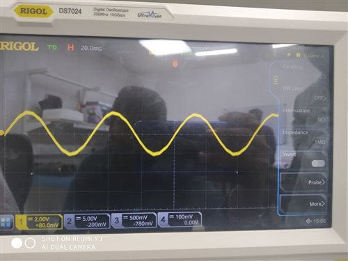
    2. we put the opamp stage as like phase currents, we didn't give reference voltage, we get the output like below, 


    HV-kit schematic phase voltages sensing:

  • 1.  Yes. The offset is used to calibrate the sensing error between three phases. You might find these values are used in the project.

    2. It's not necessary to add an amplifier for voltage sensing. Obviously, the waveform you showed above is not correct.

  • Hi thanks for the reply,

    1.we are using Estun_EMJ_04APB22_A motor, we flash lab03,04,05 my motor spin successfully, we want to control the speed of the motor, we flash lab07,but my pmsm motor running with some breaks, we changed some GPIO pins in hal.c file, ( we changed SPI port A to port B) as shown below.

    (gpio9) SPICLKA to SPICLKB (gpio58)

    (gpio11) SPISTEB to SPISTEB(gpio59)

    (gpio16) SPI-SIMOA to SPI-SIMOB(gpio56)

    (gpio17) SPI-SOMIA to SPI-SOMIB(gpio 31) 

    2. we also add change gpio28 and 29 for UART portA

    3. can you please help me to control the speed of my motor?

    4. is that above changed gpio pins effect other part of the code?

    thank you

  • Are you using the TI EVM kit? Or your own board? And changes on the TI EVM kit if you are using it?

    Did the lab07 run the motor well if you didn't change anything in the example lab? The lab07 should be fine for controlling the speed of the motor if the motor parameters are set correctly in the user.h file. 

    You might find the hardware design files of the high voltage kit in the motor control SDK, and refer to the files to know what pins are used for motor control, and what pins are reserved for the user.  The GPIOs you mentioned above are not used for motor control.

    Btw, what PWM and control ISR frequency are you using? Is there any other ISR used in the project? How many codes did you add to the control ISR?

  • Hi,thanks for the reply,

    1. Yes we are using my own board. 

    2. we using inline current sense method

    3. my motor run in lab03 & lab04,in the below  i have attached the phase current and phase voltage waveforms. we are using Estun_EMJ_04APB22_A motor

    4.we flash the lab07 and we set the watch window expressions as below 

     motorVars.flagEnableOffsetCalc” = 1
    motorVars.flagEnableSys” = 1
    motorVars.flagRunIdentAndOnLine” = 1
    motorVars.flagEnableForceAngle” = 0

    4. we changed  motorVars.speedRef_Hz  for different values my pmsm motor run successfully in different speeds, but my phase current and phase voltgae waveforms are looking very bad, we tried this lab with TI-HV-kit also we get the waveforms as like below.

    5. can you help me to solve this?

    lab04 current and phase voltage waveforms:

    VR:

    VY:

    VB:

    Ir:

    Iy:

    Ib:

    Lab07 wave forms:

    Iy:

    Ib:

  • Could you please have a brief description of the waveforms you posted? Which are based on the TI high voltage kit? Which are tested with your own board?

    You have to check the current and voltage sensing circuit design on your board if the motor runs well on TI high voltage kit, but has bad performance on your own board.

  • Thanks for the reply, 

    The images all are taken with my board. 

    The first 6images from lab04 and last 3 images from lab07, in lab04 there is no noise in the waveform, but in lab07 we get noise. 

    Thank you

  • Since you have the Estun_EMJ_04APB22_A motor, you might use the example lab05 to identify the motor on the TI high voltage kit, and see if the motor identification parameters are close to the value in user.h.

    And then do the same process on your own board. If the identified motor parameters are much different from the example value, you have to check/debug the current and voltage sensing circuit.

  • Thanks for the reply

    We have a single phase input with PFC circuit, with which I can control the DC-bus voltage Level that goes to Inverter. We plan to set the RYB phase voltages amplitude to a particular level, what parameters directly effect the Phase RYB output voltages?

    Thank you

  • It doesn't matter since the motor is controlled with FOC, just enable the dc bus voltage is high enough for the required torque output that depends on the specification of the motor. You might set the target dc bus voltage is greater than the rated voltage of the motor * sqrt(2), but it is less than 400V.

  • Hi thanks for the reply, 

    we could spin my motor using lab03 and lab04, now we are going to lab05,(motor identification), we didn’t get the RS and flux,Ld,Lq, same as user.h, after motorVars.flagMotorIdentified set to 1 , we set the motorVars.flagRunIdentAndOnLine to 1, my motor spin but not smoothly.

    Can you please help me to solve this problem?

  • What's the difference between the identification parameters and the one in user.h? Did the motor spin smoothly during the identification process?

  • Hi thanks for the reply,
    1. Below are my motro paramteres presented in user.h
    #define USER_MOTOR_Rs_Ohm (2.26793718)
    #define USER_MOTOR_Ls_d_H (0.00808008015)
    #define USER_MOTOR_Ls_q_H (0.00808008015)
    #define USER_MOTOR_RATED_FLUX_VpHz (0.387036026)
    We get below in watch window
    RS: 0.001000
    Ls_d: 0.013206
    Ls_q: 0.013206
    Flux_VpHz: 78
    2. Yes my motor run smoothly in identification process

    Thank you

  • It seems like the motor is not identified successfully, the Rs and Flux_VpHz are very strange, I don't the motor can spin smoothly if you are using the Estun_EMJ_04APB22_A. You might use a multimeter to measure the Rs, and please use the original example lab without any changes to identify again.

  • Hi, thanks for the reply,

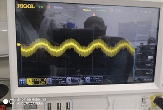
    We have  used the original example lab without any changes on Hv-kit , we run the lab03, lab04 and lab05, we get the below results,we done all these labs with inline current sensing.in lab05 at rated flux identification process my motor run smoothly, but in Ls identification state motor spin with vibration , after done with  identification process  we spin the motor, it is rotating smoothly,but phase current wave forms are very bad,can you please give me the suggestion?

    Watch window results:                         

    Rs: 4.04

    Ls_d-H : 0.0138513039

    Ls_q-H : 0.0138513039

    Flux:0.378

    In lab05 we get below wave forms:

    phase currents:

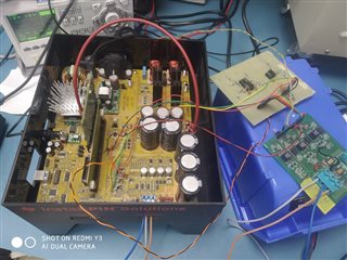
    Below is my test setup:

    thank you

    thank  you

  • You have to check the current or voltage sensing, and the scale value settings since you change the board. It seems like the connection wires for current/voltage sensing are too long which could affect the sampling performance.

  • HI, thanks for the reply,

    We didn't change the voltage sensing circuit, we have changed only the current sensing circuit for inline sensing.

     #define USER_ADC_FULL_SCALE_VOLTAGE_V         ((float32_t)(409.0))

    thank you

  • Hi DS,

    The Kelvin connections to shunts should be kept short <1cm if possible & same length.  Perhaps set scope for 1k samples deep, not 10K to get better clarity. Try to use twisted wires (shield) with one on ground tied to one PCB or the other for current signals going back to HV kit. Perhaps you may need to adjust ADC full scale current for your remote inline sensors to get R/L RS ohms corrected.

  • The current sensing signals are more important and critical for motor control. You might shorten the connection wires and try to use the shield twisted-pair lines to connect your current sensing board to the controlCard, and make sure the scale current value is calculated correctly according to the hardware.

  • Hi thanks for the reply,
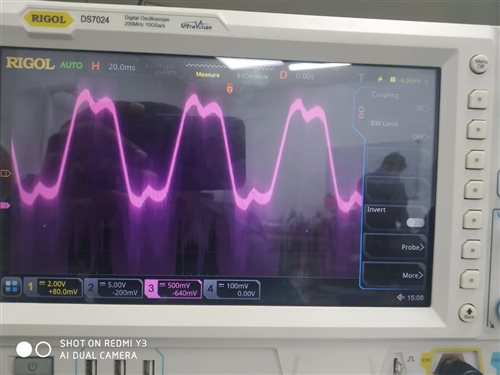
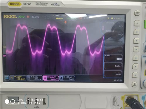
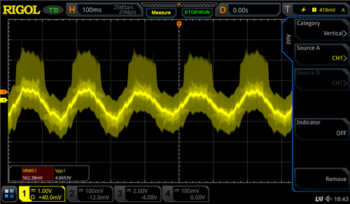
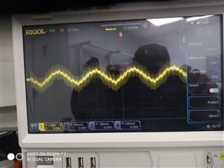
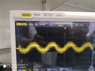
    We get the correct motor parameters in lab05, we set that identified values in user.h, and now we run the lab07 we get the current waveforms like below, we get the PWM(15KHz)frequency at the peak of the sine wave, we didn’t get the pure sine wave.
    1. Can you please help me to solve this problem?

    Thank you

  • This is normal state. The current will follow the BEM shape of the motor, it's not a pure sinusoidal always, especially at low speed, or light load, or the speed over the rated value.

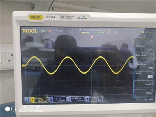
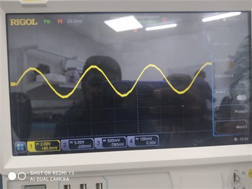
  • we get the current waveforms like below

    Looks like scope is aliasing from odd horizontal sweep or trigger timing. Perhaps your scope is triggering on a harmonic of the actual AC signal causing channel aliasing? Does signal become more clear to reduce acquisition sample depth to 1KSPS versus 10-100KSPS?  

  • You might run the motor to a high speed, and add a load to the shaft of the motor. The waveforms should be much similar to sinusoidal shape.

    And you can set the oscilloscope as GI mentioned which could help to get a clear waveform as well.