Because of the holidays, TI E2E™ design support forum responses will be delayed from Dec. 25 through Jan. 2. Thank you for your patience.

This thread has been locked.

If you have a related question, please click the "Ask a related question" button in the top right corner. The newly created question will be automatically linked to this question.

TMS320F28069M: Debug and deploy code into TMS320F28069M.

Part Number: TMS320F28069M
Other Parts Discussed in Thread: TI-CGT, CCSTUDIO, LAUNCHXL-F28069M

Dear Sir,

During the use of TMS320F28069M, code is not being deployed anymore. Supply and hardware were verified. Continuity is available at all points (verified using multimeter). 3 methods of code deploying was being used: MATLAB, C2Prog (via FTDI chip - 3.3V 5V FT232RL FTDI USB to TTL Serial Adapter) and Code Composer Studio by me. However now no method of code deployment is working now. 

A Colleague of mine analysed it and suggested that maybe due to power fluctuation in supply, uC chip has locked itself. I am not able to unlock or debug it now.

Kindly suggest how to debug it.

If you have any detailed application note, kindly share it.

Thanking you,

Regards,

Aditi Bhatta.

  • Aditi,

    Thanks for reaching out to the E2E.  Is there is an unstable power supply or XRSn event during flash erase or programmation there can be scenarios where the password locations(in flash) get written and the device will be "locked"

    However, if you haven't re-programmed the flash in some time, this should not be the case.  Did this occur after a recent flash erase/program operation?

    Are you able to connect to the device via JTAG?  If so we can manually check the password locations to verify if this is the issue.  Once connected we need to look at memory locations 0x3F7FF8 -0x3F7FFF.  If these are zero, then the device is locked with a password.  If this is the case, and the password is unknown, then the device is permanently locked an all secure memories will be locked as well.  The only option at that point is to replace the device.

    Note that you may need to place the device in Wait Boot Mode to connect(if the CSM is active).  This can be done by pulling GPIO34 low and GPIO37 high before powering the device.

    Let me know what you find and we can go from there.

    Best,

    Matthew

  • Matthew,

    Before this issued cropped up, I had deployed code many times into launchpad, and got the results successfully, on the same day. It was in use from many days.

    I tried to run jtag. but was unsuccessful in it. I got the following msg while trying to connect launchpad using CCS:

    CCS Connect to target output:

    Error connecting to the target:
    (Error -1015 @ 0x0)
    Device is not responding to the request. Device may be locked, or the debug probe connection may be unreliable.
    Unlock the device if possible (e.g. use wait in reset mode, and power-cycle the board).
    If error persists, confirm configuration and/or try more reliable JTAG settings (e.g. lower TCLK).
    (Emulation package 6.0.407.3

    [Start: Texas Instruments XDS100v2 USB Debug Probe_0]

    Execute the command:

    %ccs_base%/common/uscif/dbgjtag -f %boarddatafile% -rv -o -F inform,logfile=yes -S pathlength -S integrity

    [Result]


    -----[Print the board config pathname(s)]------------------------------------

    C:\Users\prasa\AppData\Local\TEXASI~1\CCS\
    ti\0\0\BrdDat\testBoard.dat

    -----[Print the reset-command software log-file]-----------------------------

    This utility has selected a 100- or 510-class product.
    This utility will load the adapter 'jioserdesusb.dll'.
    The library build date was 'Jul 27 2016'.
    The library build time was '18:31:37'.
    The library package version is '6.0.407.3'.
    The library component version is '35.35.0.0'.
    The controller does not use a programmable FPGA.
    The controller has a version number of '4' (0x00000004).
    The controller has an insertion length of '0' (0x00000000).
    This utility will attempt to reset the controller.
    This utility has successfully reset the controller.

    -----[Print the reset-command hardware log-file]-----------------------------

    The scan-path will be reset by toggling the JTAG TRST signal.
    The controller is the FTDI FT2232 with USB interface.
    The link from controller to target is direct (without cable).
    The software is configured for FTDI FT2232 features.
    The controller cannot monitor the value on the EMU[0] pin.
    The controller cannot monitor the value on the EMU[1] pin.
    The controller cannot control the timing on output pins.
    The controller cannot control the timing on input pins.
    The scan-path link-delay has been set to exactly '0' (0x0000).

    -----[The log-file for the JTAG TCLK output generated from the PLL]----------

    There is no hardware for programming the JTAG TCLK frequency.

    -----[Measure the source and frequency of the final JTAG TCLKR input]--------

    There is no hardware for measuring the JTAG TCLK frequency.

    -----[Perform the standard path-length test on the JTAG IR and DR]-----------

    This path-length test uses blocks of 64 32-bit words.

    The test for the JTAG IR instruction path-length succeeded.
    The JTAG IR instruction path-length is 38 bits.

    The test for the JTAG DR bypass path-length succeeded.
    The JTAG DR bypass path-length is 1 bits.

    -----[Perform the Integrity scan-test on the JTAG IR]------------------------

    This test will use blocks of 64 32-bit words.
    This test will be applied just once.

    Do a test using 0xFFFFFFFF.
    Scan tests: 1, skipped: 0, failed: 0
    Do a test using 0x00000000.
    Scan tests: 2, skipped: 0, failed: 0
    Do a test using 0xFE03E0E2.
    Scan tests: 3, skipped: 0, failed: 0
    Do a test using 0x01FC1F1D.
    Scan tests: 4, skipped: 0, failed: 0
    Do a test using 0x5533CCAA.
    Scan tests: 5, skipped: 0, failed: 0
    Do a test using 0xAACC3355.
    Scan tests: 6, skipped: 0, failed: 0
    All of the values were scanned correctly.

    The JTAG IR Integrity scan-test has succeeded.

    -----[Perform the Integrity scan-test on the JTAG DR]------------------------

    This test will use blocks of 64 32-bit words.
    This test will be applied just once.

    Do a test using 0xFFFFFFFF.
    Scan tests: 1, skipped: 0, failed: 0
    Do a test using 0x00000000.
    Scan tests: 2, skipped: 0, failed: 0
    Do a test using 0xFE03E0E2.
    Scan tests: 3, skipped: 0, failed: 0
    Do a test using 0x01FC1F1D.
    Scan tests: 4, skipped: 0, failed: 0
    Do a test using 0x5533CCAA.
    Scan tests: 5, skipped: 0, failed: 0
    Do a test using 0xAACC3355.
    Scan tests: 6, skipped: 0, failed: 0
    All of the values were scanned correctly.

    The JTAG DR Integrity scan-test has succeeded.

    [End: Texas Instruments XDS100v2 USB Debug Probe_0]

    <Linking>
    "### Created: ../LET_TEST_R_2.out"
    "### Invoking postbuild tool "Hex Converter" on "../LET_TEST_R_2.out"..."
    C:/PROGRA~3/MATLAB/SUPPOR~1/R2019a_1/3P778C~1.INS/TIC200~1.INS/TI-CGT~1.LTS/bin/hex2000 -i "../LET_TEST_R_2.out" -o "../LET_TEST_R_2.hex" -order MS -romwidth 16 -q
    "### Done Invoking postbuild tool "Hex Converter" ..."
    "### Successfully generated all binary outputs."

    G:\ad\matlab_rename\edrive\pwm\led_toggle\led_casino\every_day_report\gpio_pwm\LET_TEST_R_2_ert_rtw>exit 0
    Downloading program to the target hardware...
    ### Build procedure for model: 'LET_TEST_R_2' aborted due to an error.
    The following error occurred during deployment to your hardware board:

    Debug Server Scripting (DSS) error:
    *** User inputs:
    Target Configuration: C:\PROGRA~3\MATLAB\SUPPOR~1\R2019a_1\toolbox\target\SUPPOR~1\tic2000/CCS_CO~1/F28069~1.CCX
    Program Name: G:\ad\matlab_rename\edrive\pwm\led_toggle\led_casino\every_day_report\gpio_pwm\LET_TEST_R_2.out
    Board Name: *
    CPU Name: unspecified (connect to first CPU)

    *** Starting debug session...
    *** Debug Session Name: Texas Instruments XDS100v1 USB Debug Probe_0/C28xx
    *** Board Name: Texas Instruments XDS100v1 USB Debug Probe_0
    *** CPU Name: C28xx

    *** Connecting to target...
    SEVERE: C28xx: Error connecting to the target: (Error -1015 @ 0x0) Device is not responding to the request. Device may be locked, or the debug probe connection may be unreliable. Unlock the device if possible (e.g. use wait in reset mode, and power-cycle the board). If error persists, confirm configuration and/or try more reliable JTAG settings (e.g. lower TCLK). (Emulation package 6.0.407.3)

    SEVERE: emulation failure occurred
    SEVERE: Error connecting to the target: emulation failure occurred
    SEVERE: Cannot perform operation, target is not connected.
    SEVERE: Error reseting target: Cannot perform operation, target is not connected.
    org.mozilla.javascript.WrappedException: Wrapped com.ti.ccstudio.scripting.environment.ScriptingException: Error reseting target: Cannot perform operation, target is not connected. (C:\PROGRA~3\MATLAB\SUPPOR~1\R2019a_1\toolbox\target\SUPPOR~1\tic2000/CCS_CO~1/RUNPRO~2.JS#93)
    at org.mozilla.javascript.Context.throwAsScriptRuntimeEx(Context.java:1693)
    at org.mozilla.javascript.MemberBox.invoke(MemberBox.java:160)
    at org.mozilla.javascript.NativeJavaMethod.call(NativeJavaMethod.java:204)
    at org.mozilla.javascript.optimizer.OptRuntime.callProp0(OptRuntime.java:119)
    at org.mozilla.javascript.gen.c1._c0(C:\PROGRA~3\MATLAB\SUPPOR~1\R2019a_1\toolbox\target\SUPPOR~1\tic2000/CCS_CO~1/RUNPRO~2.JS:93)
    at org.mozilla.javascript.gen.c1.call(C:\PROGRA~3\MATLAB\SUPPOR~1\R2019a_1\toolbox\target\SUPPOR~1\tic2000/CCS_CO~1/RUNPRO~2.JS)
    at org.mozilla.javascript.ContextFactory.doTopCall(ContextFactory.java:340)
    at org.mozilla.javascript.ScriptRuntime.doTopCall(ScriptRuntime.java:2758)
    at org.mozilla.javascript.gen.c1.call(C:\PROGRA~3\MATLAB\SUPPOR~1\R2019a_1\toolbox\target\SUPPOR~1\tic2000/CCS_CO~1/RUNPRO~2.JS)
    at org.mozilla.javascript.gen.c1.exec(C:\PROGRA~3\MATLAB\SUPPOR~1\R2019a_1\toolbox\target\SUPPOR~1\tic2000/CCS_CO~1/RUNPRO~2.JS)
    at org.mozilla.javascript.tools.shell.Main.evaluateScript(Main.java:503)
    at org.mozilla.javascript.tools.shell.Main.processFileSecure(Main.java:425)
    at org.mozilla.javascript.tools.shell.Main.processFile(Main.java:391)
    at org.mozilla.javascript.tools.shell.Main.processSource(Main.java:382)
    at org.mozilla.javascript.tools.shell.Main.processFiles(Main.java:179)
    at org.mozilla.javascript.tools.shell.Main$IProxy.run(Main.java:100)
    at org.mozilla.javascript.Context.call(Context.java:528)
    at org.mozilla.javascript.ContextFactory.call(ContextFactory.java:450)
    at org.mozilla.javascript.tools.shell.Main.exec(Main.java:162)
    at com.ti.ccstudio.apps.internal.scripting.RunScript$1.run(RunScript.java:88)
    Caused by: com.ti.ccstudio.scripting.environment.ScriptingException: Error reseting target: Cannot perform operation, target is not connected.
    at com.ti.debug.engine.scripting.Target.reset(Target.java:622)
    at sun.reflect.NativeMethodAccessorImpl.invoke0(Native Method)
    at sun.reflect.NativeMethodAccessorImpl.invoke(NativeMethodAccessorImpl.java:57)
    at sun.reflect.DelegatingMethodAccessorImpl.invoke(DelegatingMethodAccessorImpl.java:43)
    at java.lang.reflect.Method.invoke(Method.java:606)
    at org.mozilla.javascript.MemberBox.invoke(MemberBox.java:145)
    ... 18 more
    .


  • Dear Matthew,

    I have shared the results of CCS connect to target, test Connection and MATLAB deploy to hardware. 

    Memory address suggested by you is not accessible by me. 

    Kindly suggest how to proceed.

    Regards,

    Aditi.

  • Aditi,

    Can we configure switch S1 on the launch pad to Wait boot as shown in the below picture(leave Switch 3 in H position so XDS100v2 controls it).  Then just right click on the ccxml in CCS and "Launch target config" then right click on the C28x and connect to the target.  We should then be able to look at the memory contents I mentioned in the previous post.  We need to connect this way to avoid CCS from autoloading code when you click the "debug" button.

    This application note may prove useful as well.

    Best,
    Matthew

  • Mathew,

    Results of Test connection in CCS are :

    [Start: Texas Instruments XDS100v2 USB Debug Probe_0]

    Execute the command:

    %ccs_base%/common/uscif/dbgjtag -f %boarddatafile% -rv -o -F inform,logfile=yes -S pathlength -S integrity

    [Result]


    -----[Print the board config pathname(s)]------------------------------------

    C:\Users\prasa\AppData\Local\TEXASI~1\CCS\
    ti\0\0\BrdDat\testBoard.dat

    -----[Print the reset-command software log-file]-----------------------------

    This utility has selected a 100- or 510-class product.
    This utility will load the adapter 'jioserdesusb.dll'.
    The library build date was 'Jul 27 2016'.
    The library build time was '18:31:37'.
    The library package version is '6.0.407.3'.
    The library component version is '35.35.0.0'.
    The controller does not use a programmable FPGA.
    The controller has a version number of '4' (0x00000004).
    The controller has an insertion length of '0' (0x00000000).
    This utility will attempt to reset the controller.
    This utility has successfully reset the controller.

    -----[Print the reset-command hardware log-file]-----------------------------

    The scan-path will be reset by toggling the JTAG TRST signal.
    The controller is the FTDI FT2232 with USB interface.
    The link from controller to target is direct (without cable).
    The software is configured for FTDI FT2232 features.
    The controller cannot monitor the value on the EMU[0] pin.
    The controller cannot monitor the value on the EMU[1] pin.
    The controller cannot control the timing on output pins.
    The controller cannot control the timing on input pins.
    The scan-path link-delay has been set to exactly '0' (0x0000).

    -----[The log-file for the JTAG TCLK output generated from the PLL]----------

    There is no hardware for programming the JTAG TCLK frequency.

    -----[Measure the source and frequency of the final JTAG TCLKR input]--------

    There is no hardware for measuring the JTAG TCLK frequency.

    -----[Perform the standard path-length test on the JTAG IR and DR]-----------

    This path-length test uses blocks of 64 32-bit words.

    The test for the JTAG IR instruction path-length succeeded.
    The JTAG IR instruction path-length is 38 bits.

    The test for the JTAG DR bypass path-length succeeded.
    The JTAG DR bypass path-length is 1 bits.

    -----[Perform the Integrity scan-test on the JTAG IR]------------------------

    This test will use blocks of 64 32-bit words.
    This test will be applied just once.

    Do a test using 0xFFFFFFFF.
    Scan tests: 1, skipped: 0, failed: 0
    Do a test using 0x00000000.
    Scan tests: 2, skipped: 0, failed: 0
    Do a test using 0xFE03E0E2.
    Scan tests: 3, skipped: 0, failed: 0
    Do a test using 0x01FC1F1D.
    Scan tests: 4, skipped: 0, failed: 0
    Do a test using 0x5533CCAA.
    Scan tests: 5, skipped: 0, failed: 0
    Do a test using 0xAACC3355.
    Scan tests: 6, skipped: 0, failed: 0
    All of the values were scanned correctly.

    The JTAG IR Integrity scan-test has succeeded.

    -----[Perform the Integrity scan-test on the JTAG DR]------------------------

    This test will use blocks of 64 32-bit words.
    This test will be applied just once.

    Do a test using 0xFFFFFFFF.
    Scan tests: 1, skipped: 0, failed: 0
    Do a test using 0x00000000.
    Scan tests: 2, skipped: 0, failed: 0
    Do a test using 0xFE03E0E2.
    Scan tests: 3, skipped: 0, failed: 0
    Do a test using 0x01FC1F1D.
    Scan tests: 4, skipped: 0, failed: 0
    Do a test using 0x5533CCAA.
    Scan tests: 5, skipped: 0, failed: 0
    Do a test using 0xAACC3355.
    Scan tests: 6, skipped: 0, failed: 0
    All of the values were scanned correctly.

    The JTAG DR Integrity scan-test has succeeded.

    [End: Texas Instruments XDS100v2 USB Debug Probe_0]

  • Mathew,

    I configured the switch in wait boot mode.

    Error of "Launch Target Connection" is :

    Error connecting to the target:
    (Error -1135 @ 0x0)
    The debug probe reported an error. Confirm debug probe configuration and connections, reset the debug probe, and retry the operation.
    (Emulation package 6.0.407.3)

  • Aditi,

    Can you confirm that position 3(TRSTn) is left in the H state?  If its in the L position, the XDS100 won't control the TRSTn signal correctly.  I realize that the table is not clear on this point, sorry for any confusion.

    Best,

    Matthew

  • Mathew,

    TRSTn is in H state. 

    In response to your apology, I am new to LAUNCHPAD XL-F28069M. I am still learning how to work it out. 

    I am grateful for your patience, time and your help.

    Regards,

    Aditi.

  • Aditi,

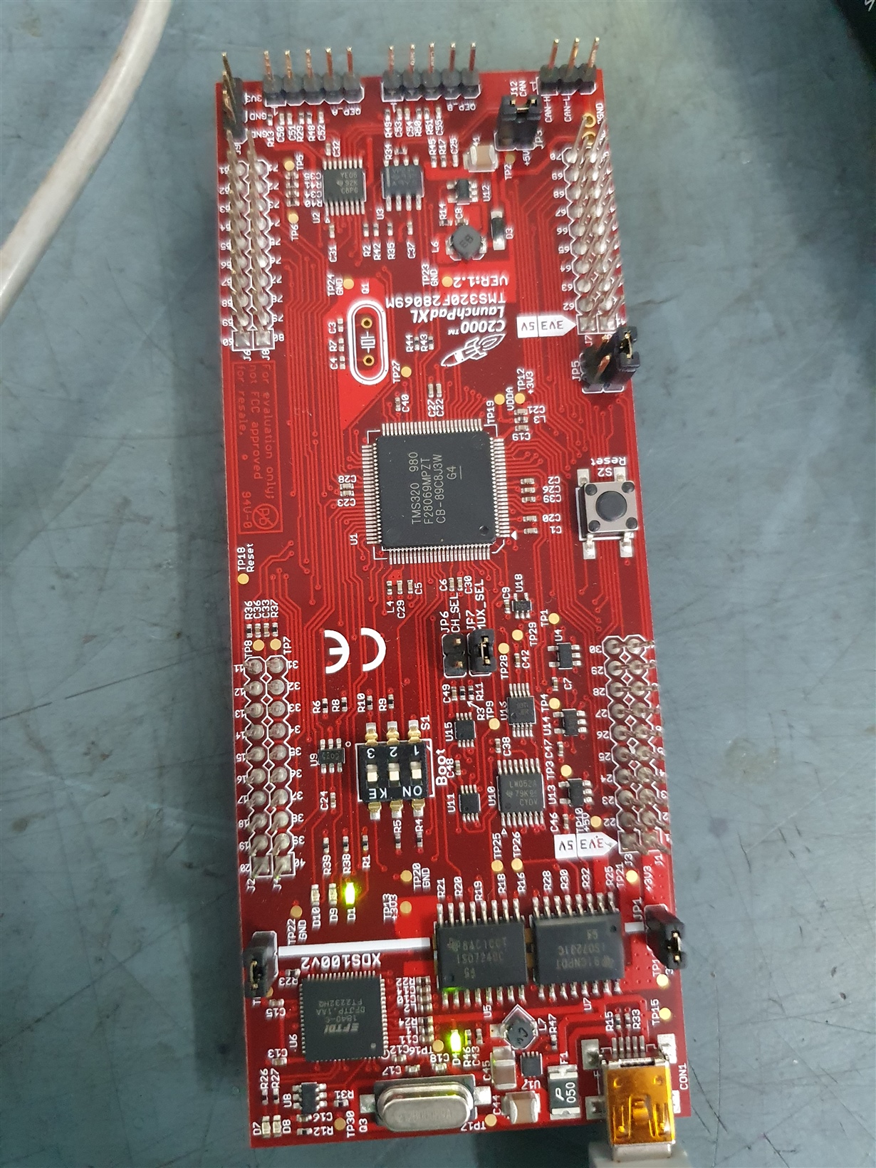
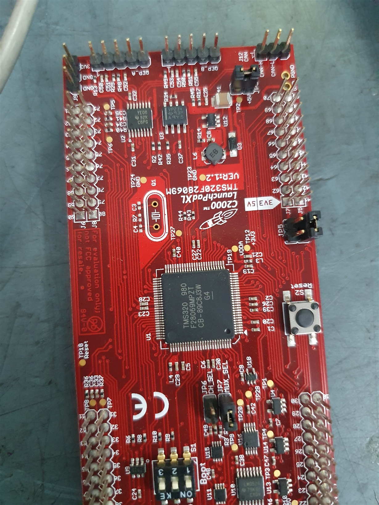
    No worries, HW debug is always a bit tricky.  Would it be possible to take a picture of the full top side of the LaunchPad with it powered and attach it to your reply?  This will help me determine if there are any other jumpers/switches/pins that need to be modified.

    Based on your earlier post, the CCS message is indicating that we have connection to the XDS100V2 that is on the LP, but no connection from it to the MCU.

    Best,
    Matthew

  • Mathew,

    Find the attachment for the pictures of Launchpad.

    Regards.

    Aditi.

  • Aditi,

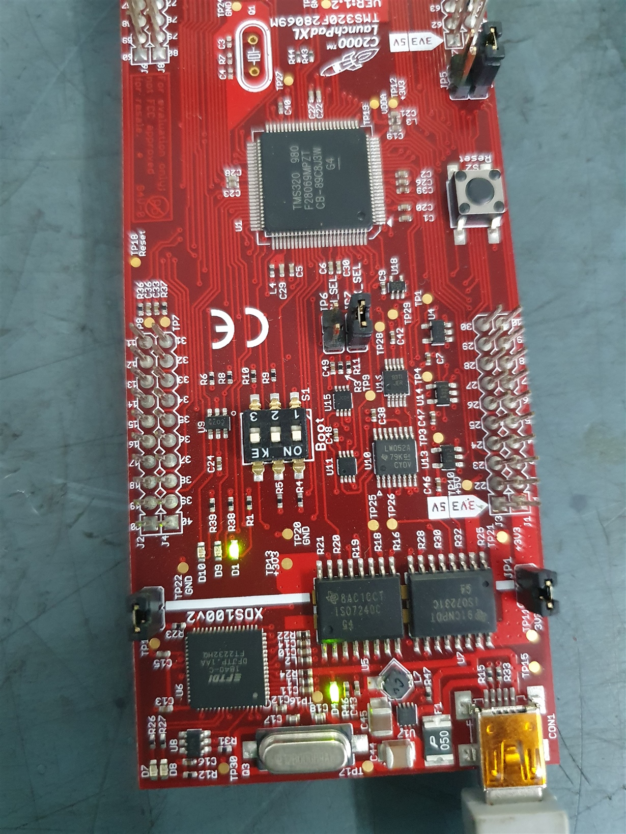
    Thanks for the pictures. On the Boot switch (S1), please move position 1 to the off/down position.  S2 and S3 are in the correct on/up positions.  This will put us in Wait boot mode and then try to connect.

    Best,

    Matthew

  • Mathew,

    I did as you told. Here is the error message on the console window of CCS :

    ComPort: Trouble Reading Memory Block at 0x0 on Page 0 of Length 0x5: Read timed out
    ComPort: Trouble Reading Memory Block at 0x0 on Page 0 of Length 0x8e: Read timed out
    C28xx: GEL Output:
    Device Calibration not complete, check if device is unlocked and recalibrate.C28xx: Error: (Error -1135 @ 0x3FF75B) The debug probe reported an error. Confirm debug probe configuration and connections, reset the debug probe, and retry the operation. (Emulation package 6.0.407.3)
    C28xx: Unable to determine target status after 20 attempts
    C28xx: Failed to remove the debug state from the target before disconnecting. There may still be breakpoint op-codes embedded in program memory. It is recommended that you reset the emulator before you connect and reload your program before you continue debugging

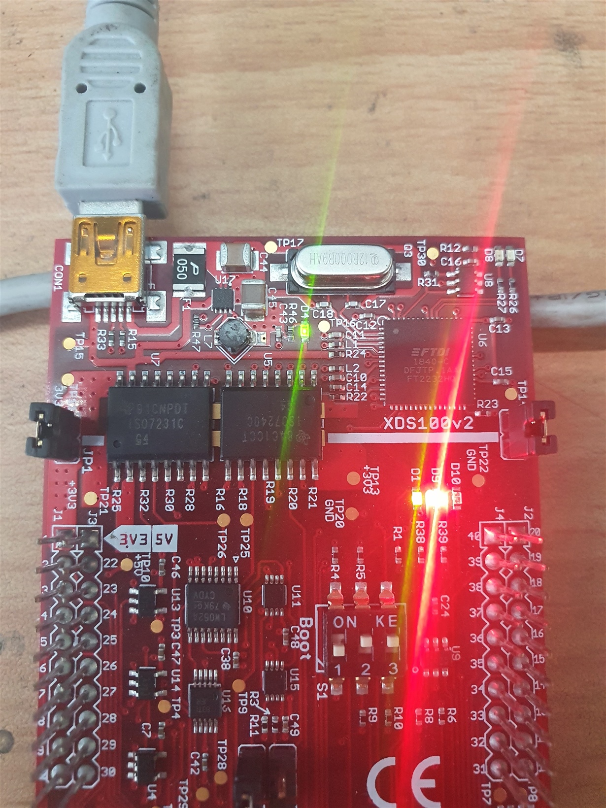
    Here is a picture of launchpad as well :

    Note: D4, D1 (green led are constantly high), D9(red led) is constantly on. D10 is off.

    Best,

    Aditi.

  • Aditi,

    I want to try two things:

    1)Remove jumper JP3(it on the bottom left of the board if you have the USB connection at the top) and re-power the board and try to connect.

    2)I'd like for you to look through this application note it will give step by step instructions to debug these connection issues.  Some we have tried, but I think it would be helpful to get a baseline and you can reply back with which step is causing the issue.

    Best,

    Matthew

  • Mathew,

    Sorry for late reply.

    After removing JP3, I tried in CCS. Result which I got is given below.

    The JTAG DR Integrity scan-test has failed.

    [End: Texas Instruments XDS100v2 USB Debug Probe_0]

    [Start: UARTConnection_0]

    Execute the command:

    The Diagnostic Command is not defined in the connection properties.

    Also another error:-

    Error connecting to the target:
    (Error -1015 @ 0x0)
    Device is not responding to the request. Device may be locked, or the debug probe connection may be unreliable. Unlock the device if possible (e.g. use wait in reset mode, and power-cycle the board). If error persists, confirm configuration and/or try more reliable JTAG settings (e.g. lower TCLK).
    (Emulation package 6.0.407.3)

    Thank you for the application note. Most of the points we have covered. Few points I need to crosscheck. I will let you know after completing it.

    Best,

    Aditi.

  • Aditi,

    We can continue debugging, but we've covered most of the common issues at this point without resolving the issue.

    It may be simpler to buy another LAUNCHXL-F28069M from the TI store, we may end up finding out something is damaged on the board which would have the same result.

    With that said, if you have more info I'll be happy to look into it with you.

    Best,

    Matthew

  • Dear Mathew,

    Thank you for your cooperation. I will contact you if any further problem arises.

    Regards,

    Aditi.