Because of the Thanksgiving holiday in the U.S., TI E2E™ design support forum responses may be delayed from November 25 through December 2. Thank you for your patience.

This thread has been locked.

If you have a related question, please click the "Ask a related question" button in the top right corner. The newly created question will be automatically linked to this question.

TMS320F28069: sin/cos encoder phase shift correction method in TIDUA05A

Part Number: TMS320F28069
Other Parts Discussed in Thread: TIDA-00176, CONTROLSUITE, C2000WARE

Hi,

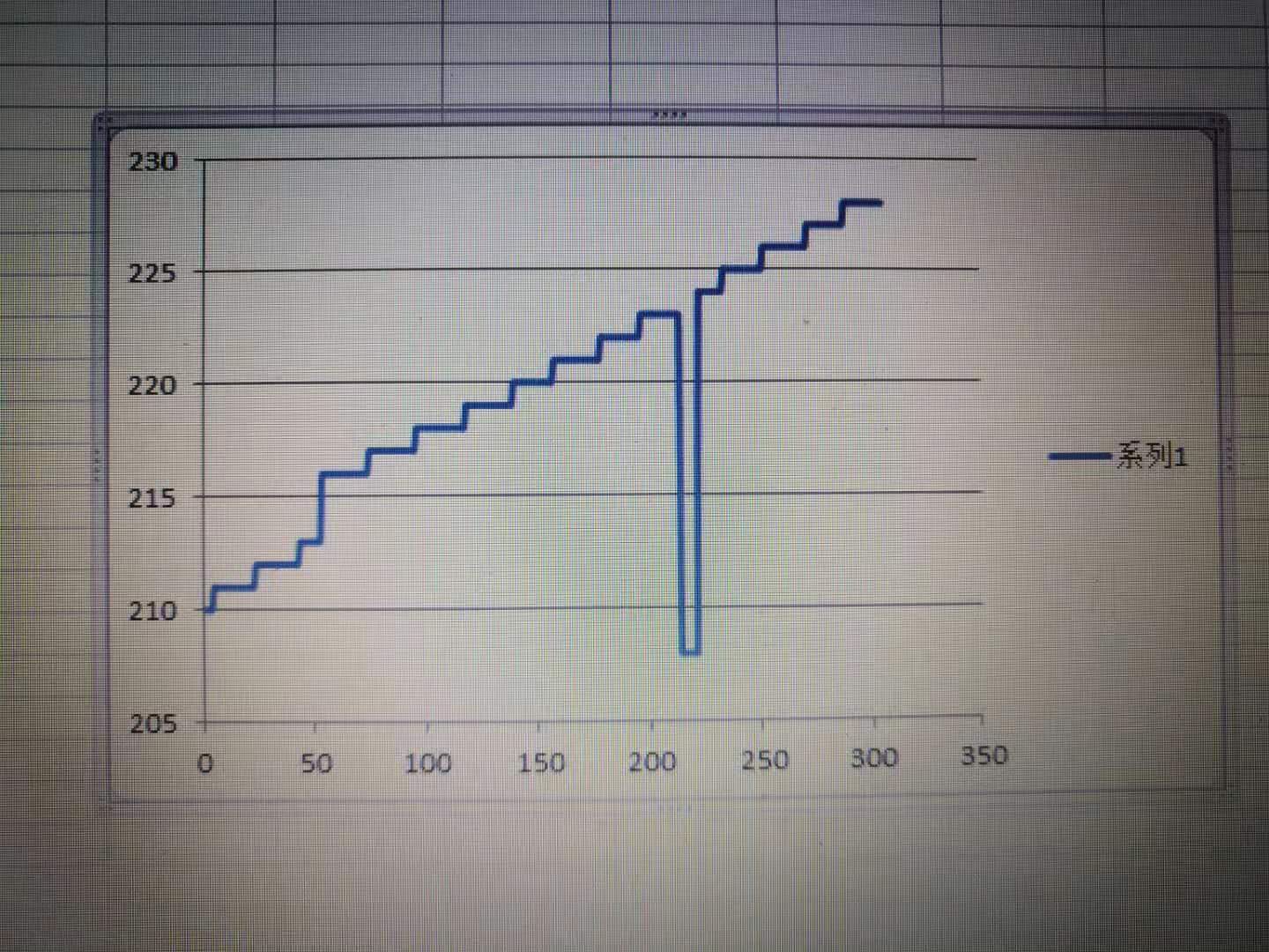
I cannot understand the sin/cos encoder  phase shift correction method in TIDUA05A.  When I programmed in DSP with this method, the position will step down when sine signal A cross the zero and then  step up when QEP(Signal A after comparator) steps/changes ,shown in the fig 3.  And as speed/frequency rises, the phase shift will increase/change, how could we correct it? Thanks.

  • Hello,

    thank your for your interest in the TIDA-00176 reference design. 

    The method to shown in figure 6 and equation (5) applies to interpolating the Sin/Cos signals based on the incremental count with the C2000 eQEP module and the interpolated interpolated phase. 

    The method in table 6 assumes the digitized signal Sin (A) or Cos (B) after the comparator lags the analog Sin and Cos signals, which are converted with the dual ADC. Therefore the interpolated angle identifies the quadrant too. The phase shift should not be larger than 90 degree. Since I left shift the incremental count I may not have the correct incremental count for the interpolation. Example

    Lets assume the phase of the sine is 2 degrees = 1st quadrant and we are in the second sine period, hence the eQEP should be 4, starting to count from 0.  However due to a phase shift of the comparator the incremental count may be delayed and hence still only be 3, hence 4th quadrant of the first period. Now when I build the interpolated position per equation (5) due to left shift my result will have an error of one period. 3 >> 2 = Period 0 + 2 degree. However it should be 4>>2= Period 1 + 2degree.     

    The phase shift through the comparator increase with the encoder speed. This is normal since the comparator even w/o hysteresis has a propagation delay. AT higher frequencies of the sine modulated encoder signals this yields a higher phase shift. Please refer to 1.4.2 in the TIDA-00176 design guide. 

    I am not sure I understand the diagram you attached. To me it looks like this is the incremental count only, as it counts in integers. If that drop is the incremental count and even without interpolation check you hardware and eQEP code.

    To debug your problem I would go step by step:

    1. Validate the encoder's Sin and Cos signals are as shown in figure 3. If e.g. the B signal is not -cosine, but + cosine correct the interpolation accordingly. 

    2. Ensure the digital signals A, B and R (if you have an index or marker signal), which are input to the eQEP module are as expected. Otherwise verify encoder and hardware. 

    3. Only test the eQEP module with your encoder standalone (no interpolation) and ensure it is counting up or down as expected. For software support please refer to the C2000 software examples in either controlSUITE or C2000Ware.

    4. If the eQEP module works as expect, calculate the phase of the Sin/Cos encoder signals and compare that phase against the incremental count. At low speed the interpolated phase should match the last 2 bits of the incremental count as per table 5. When the encoder speed and hence the frequency of the sine and cosine increases speed, check if you see the issues describe in table 6. If so apply the method.

    Regards,

    Martin Staebler


  • Hi  Martin,

    Thanks for your detailed reply. It helps a lot.

    The phase shift could be caused by the comparator lag when speed is high. This may be compensated by 'quadrant check'. But another factor to cause phase shift could be the analog signal sin/cos error. For example, when speed is very very low, every quadrant(1,2,3,4) should be theoritically 90 degrees. But actually the quadrant could be 88 degrees or 92 degrees as sin/cos signal have amplitude error and dc offset. That is, when QEP cnt changes, the  phase of sine could be 88 degrees or 92 degrees. And this bias changes as speed or tempture or line/connector resistance, etc.  Then the calculated postion (QEP<<N + atan(sin/cos) anlge in cnt ) will step up or down suddenly in the moment of 'quadrant change' or 'QEP counter change', as my figure 3 shows.  I am trying a method to fix it, but not OK yet . 

    Thanks,

    Peter

  • Hello Peter,

    thank you for the additional info. Yes, I agree the corner case you mention have to be considered. I still think the method I am using works, but of course
    depends on what you see as reference, the eQEP or the ADC atan. 

    Lets take the corner case I explained earlier considering a positive and negative phase shift between the eQEP and the ADC interpolated data.

    a) eQEP lags by 2 deg: ADC = 1 deg, eQEP = 3 (still in 4h quadrant of previous period) --> 0 ≤ Phase < 90
        INCR = 3 --> %4 = 3. Now I apply the correction method INCR+1 to get into the correct quadrant. Now I am in the correct second period and interpolate to 1
        deg, with equation (5) in the design guide.

    b) eQEP leads by 2 deg : ADC = 359 deg, eQEP =4  --> 270 ≤ Phase < 360
        INCR = 4 --> 4%4 = 0. Now I subtract one from the incremental count (=3) to get to the correct 4th quadrant of the first period. Now I apply eq. (5) and
        interpolate with 359 degree.    

    Regards,
    Martin


    eQEP = 

  • Hello Martin,

    Thanks for your reply. I will try your method and give feedbacks.

    Peter