This thread has been locked.

If you have a related question, please click the "Ask a related question" button in the top right corner. The newly created question will be automatically linked to this question.

TMS320F28027: Errata ; ADC: InitialConversion ; failure mechanism

Part Number: TMS320F28027
Other Parts Discussed in Thread: C2000WARE

Hello everybody,

I use a TMS320f28027. We have strange phenomena at our customer's, but we couldn't recreate them in the laboratory. After a software update, the customer's problem was resolved. Several things have been changed as part of the software updates. Now I'm looking for the part of the code that fixed the problems. Since I cannot recreate the problem at the moment, I am dependent on the measurements that were made for the customer. In these measurements I can see that the current in my device increases for about nine cycles for unknown reasons. For this to happen, the duty cycle would have to be calculated incorrectly. This would happen if the measured current value were wrong.

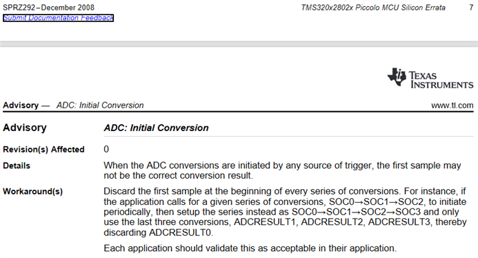
As part of the software update, a problem described in the errata was also resolved. See "ADC: InitialConversion". In the first faulty version, the result from SOC0 was used; after the update, this result was no longer used but was discarded. In the old software version, the results of the current measurement were taken from ADCRESULT0. A falsification of ADCRESULT0 would lead to incorrect current measured values. Therefore it could be that the ones described in the errata Problems related to my phenomena. To make sure that I have really fixed the cause, I would like to learn more about the failure mechanism.

What has to happen for ADCRESULT0 to be corrupted?

How severe is the disorder when it occurs?

Is a preferred value entered in the event of a malfunction? (for example 1 or 4095)

Is it plausible that nine measurements in a row will be disturbed?

What do I have to do to simulate the problems in the laboratory?

Thank you very much.

Kind regards

Joachim

  • Joachim Sinner said:
    What has to happen for ADCRESULT0 to be corrupted?

    This can happen whenever the ADC converter state machine reaches its IDLE state. When multiple SOCs are pending, the ADC state machine will service the conversions continuously without entering the IDLE state between conversions. Thus, this behavior is limited to first sample conversions.

    Joachim Sinner said:
    How severe is the disorder when it occurs?

    There is inconsistency in the behavior. A good ballpark range for modeling purposes is around +/- 500-LSBs.

    Joachim Sinner said:
    Is a preferred value entered in the event of a malfunction? (for example 1 or 4095)

    No, the error should be considered to be random.

    Joachim Sinner said:
    Is it plausible that nine measurements in a row will be disturbed?

    Nine first-samples?  Yes.  Nine simultaneously triggered continuous samples?  No, this would not be considered a first-sample issue.

    Joachim Sinner said:
    What do I have to do to simulate the problems in the laboratory?

    To get an idea of the issue, you might record and compare the ADCRESULT0 and ADCRESULT1 values from the adc_soc example from C2000Ware:  ~\C2000Ware_XXXX\device_support\f2802x\examples\structs\adc_soc

    For system modeling you might inject random error into the first sample conversion using software.

  • Thank you for the quick and extensive answer.
    I am irritated by the fact that we could not recreate the phenomena in the laboratory. So I thought that the problem occurs very rarely.
    You rate nine disruptions in a row as plausible.
    Therefore, I ask myself the following questions:
    Are there special operating conditions that favor the occurrence of the error? (Temperature, EMC, processor load, ...)
    Is it normal for the interference to falsify several measurements in a row?
    Can you estimate the maximum number of measurements that will be disturbed in a row?
    How often should the disorder occur?
    You write: There is inconsistency in the behavior. A good ballpark range for modeling purposes is around +/- 500-LSBs.
    If I expect a real ADC value with 1000 digits, this will probably be in the range of 500 - 1500 digits due to the disturbance.
    Have I interpreted your statement correctly?
    Many Thanks
    Best regards
    Joachim
  • Joachim Sinner said:
    Are there special operating conditions that favor the occurrence of the error? (Temperature, EMC, processor load, ...)

    I don't think that this was characterized because a workaround was identified.

    Joachim Sinner said:
    Is it normal for the interference to falsify several measurements in a row?
    Can you estimate the maximum number of measurements that will be disturbed in a row?
    How often should the disorder occur?

    The issue is linked to the state machine so I would not be surprised to find error in each first sample.

    Joachim Sinner said:
    You write: There is inconsistency in the behavior. A good ballpark range for modeling purposes is around +/- 500-LSBs.
    If I expect a real ADC value with 1000 digits, this will probably be in the range of 500 - 1500 digits due to the disturbance.
    Have I interpreted your statement correctly?

    Yes, with the additional clarification that I consider +/- 500-LSBs to be a good ballpark for modeling pessimistic outcomes in a system that is not discarding the first sample. From my own experience, the errors are often much smaller like +/- 15-LSBs. I would not assume that the errors are predictable or consistent between devices and board designs.

    For the assessment that I think you are seeking, I recommend logging the difference between the first and second samples in a running system. That will remove most of the speculation and make it possible to observe the amount of error that would be introduced for that system.

  • Many thank
    I will measure my system as you suggested. To do this, I will compare ADC0 and ADC1 with each other.
    I will let you know as soon as the results are available.
    Best regards
    Joachim
  • Hello tlee,

    I ran my program and watched the results in ADCResult0 and ADCResult1. Both worked with the same input. In addition, I extended my code by an If loop that is run through when the value falls below a defined value of ADCResult0. The program ran in debug mode in CCS. I had set a breakpoint in the If loop.


    During the first run, the ADC input was set in such a way that a value of approx. 800 digits was to be expected.

    On ADCResult0 I could observe values ​​in the range from 796 - 798.

    On ADCResult1 I was able to observe I observe values ​​in the range from 798 - 801.

    With a value ADCResult0 <700, the If loop would have been entered. This never happened. I couldn't provoke the problem with heat and cold. Changing the other ADC channels also had no effect. The experiment ran for about 4 hours.


    In the second run, the ADC input was set in such a way that a value of approx. 3200 digits was to be expected.

    On ADCResult0 I could observe values ​​in the range from 3197 - 3201.

    On ADCResult1 I could see values ​​in the range of Observe 3202 - 3204.

    With a value ADCResult0 <3100, the If loop would have been entered. This never happened. The experiment ran for about 2 hours.


    Can it be that the error does not occur in Debug Mode?

    (I am using an XDS100v1 USB Debug Probe.)


    Best Regards

    Joachim

  • Joachim,

    The ADC converter should not be affected by the debugger when the device is free-running.

    It may make sense to revisit the original issue since your observations are not lining up with the first-sample observations.

    I have some thoughts that might help to better characterize the current excursion:

    • When you say that 9 measurements in a row are affected, is this isolated to just the first SOC that is periodically triggered across 9 control cycles?  Are the other measurements correct?
    • What is the cycle frequency?
    • Is it possible to tell if the measurement error is present for all 9 cycles or if it just takes that long for the control algorithm to recover from an excursion?  Is there a way to back-calculate the magnitude of ADC error that would be required to produce the excursion?
    • Is there any other system activity that might coincide with the 9-cycle period?  For example, periodic offset trim?
    • How often did the excursion happen?  Was it on multiple systems?

    -Tommy

  • Hello Tommy,

    I couldn't see the problem in the lab. But I know from the customer measurements that the current increases for about 9 cycles for unknown reasons, which indicates a miscalculation of the duty cycle. In the old software the current is measured with ADC0. An incorrect measurement could be responsible. In such a scenario, ADC0 should give incorrect results about 9 times in a row. I have no knowledge of the quality of the other measurements.


    We work with a clock frequency of 15 kHz - 7.5 kHz. The ADC uses the double update.


    The control algorithm is calculated in every cycle. To explain the observed duty cycle, the current measurement would have to be way too low or the current setpoint way too high (I have no idea how that could happen).


    I can observe an increase in current over the 9 cycles, which does not necessarily mean that all 9 measurements are disturbed. However, several measurements must be disturbed, otherwise the event would not last as long.

     I looked through the measurements again and also found events that lasted shorter.


    I tried to determine the initial conditions using an example of an event. I would have expected an ADC result value of 2470. In order to be able to explain the reaction of the controller on the basis of a measurement error, an ADC result value of 1362 (or lower) would have been necessary.


    We do not use "periodic offset trim". But I cannot rule out that other parts of the system are responsible for the problem. Do you have any other suggestions?


    The problem occurs irregularly, once two events could be observed at an interval of 100 ms. But we also had phases with 3 hours of operation without the phenomenon occurring. Different systems were affected.


    As I said, the problem no longer occurs after the software update, although it is unclear whether the problem has really been resolved or whether by chance we no longer observed the problem with the new software. So I'm looking for a mechanism that explains why the new software fixes the problems. The problem described in the errata seemed to fit. But I can't be sure yet.


    Best Regards

    Joachim

  • Joachim,

    This is certainly a tricky one to unravel.  I'll list some thoughts.

    9 cycles at 15-kHz is a considerable amount of time and 1000-LSBs is a significant amount of error.  It feels to me more like an external system influence rather than internal state-machine quirk.

    Another benefit of discarding the first sample is that cross-talk between conversions is potentially reduced because the sampling capacitor has more time to settle at the input voltage.  However, you should be able to see this effect when comparing the first and sample conversions so it is probably not applicable here.

    There is a known behavior where ADC conversions can be corrupted if input voltages outside of the VSSA to VDDA range are applied to any of the analog pins.  Excess charge is shunted from the input pin to VSSA and VDDA.  For this scenario, I would expect all conversions to be corrupted during the shunting state.

    Are any AIOs being used?  They can provide a noise path if there is a lot of pin activity.

    Is external reference used?  That could be another resource to consider.

    Is it possible to experiment with the old software?  It may provide some more clues.  Or the individual changes can be evaluated in isolation.  Or maybe run two susceptible systems side-by-side (one with old and the other with new software) to see if there may be some environment influence.

    -Tommy

  • Hello Tommy,

    yes this is really a tough question. I will look for another source of error. Because, I couldn't prove the effect and you suspect another cause.

    We will of course continue to discard the first measurement in our current SW.

    I rule out any influence via EMC, because after the software update the problem seemed to be resolved. We use an AOI as an exit. In its use, however, there is no difference between the new and the old SW. We do not use an external reference.

    It is possible to experiment with the old software. However, we do not have access to the customer machine, and so far the errors have only shown up there.

    Can you answer the last question for me, since which year the problem "initial conversion" was announced via the errata document?

    Many thanks Joachim

  • since which year the problem "initial conversion" was announced via the errata document?

    The Initial Conversion advisory was first published in December 2008:

  • Thank you

    Best Regards

    Joachim