This thread has been locked.

If you have a related question, please click the "Ask a related question" button in the top right corner. The newly created question will be automatically linked to this question.

TMS320F28035: Clearing PIEIFR (interrupt servicing)

Part Number: TMS320F28035
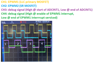
I am using F28035 for LLC converter control.
I am having a problem with two of the interrupts -- ADCINT1 and EPWM1;
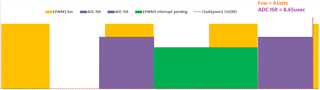
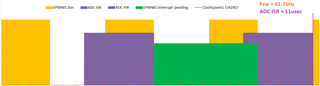
  ADCINT1 interrupt = used for ADC and loop calculations; period = 40kHz; triggered by EPWM3;
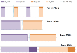
  EPWM1 interrupt = used to updated EPWM1&2 parameters; shadowed; triggered by EPWM1 count = CAU;
EPWM1 interrupt is enabled right after the ADCINT1 interrupt;
Note that ADCINT1 is not sync'd to EPWM1&2;
I am encountering problems when the EPWM1 interrupt remains pending when the ADCINT1 interrupt gets serviced on its next ADC cycle.
The problem manifests as EPWM1 and/or EPWM2 parameters not updated correctly at the same time.
I have played around with different EPWM1 settings and the problem persists.
There will always be some transient condition leading to a change in switching frequency wherein the problem will be caught.
I have read about TMS320F2803x Piccolo TRM's section 1.6.3.1. Rule #1;
I want to use it to clear the pending EPWM1 interrupt at the start of ADCINT1 routine.
But...
1) Does implementing Rule#1 solve my problem?
2) Do you have an example on how to implement it?
3) Can the EPWM1 interrupt's PIEIFR be cleared while inside ADCINT1?
4) Any other possibly better ideas? Basically, I need to freely and correctly update EPWM1&2 parameters after ADCISR calculations;
Thanks,
dom
  • 1) Does implementing Rule#1 solve my problem?

    I do not follow how Rule #1 relates to your issue. Direct modification of PIEIFR and PIEIER bits is uncommon during normal system operation. Can you elaborate on why and how you are doing this?

    2) Do you have an example on how to implement it?

    The sequence of operations listed under Rule 1 is recommended.

    3) Can the EPWM1 interrupt's PIEIFR be cleared while inside ADCINT1?

    Rule 1 would advise against doing this directly using software writes.

    4) Any other possibly better ideas? Basically, I need to freely and correctly update EPWM1&2 parameters after ADCISR calculations;

    If the parameters are shadow-loaded, I would recommend updating the register values in the ADC ISR and allowing the EPWM registers to auto-update when the shadow-load condition is met.

  • Hi,
    Thanks for the reply.
    Please see my responses below.
    Regards,
    Dom

    1) Does implementing Rule#1 solve my problem?
    I do not follow how Rule #1 relates to your issue. Direct modification of PIEIFR and PIEIER bits is uncommon during normal system operation. Can you elaborate on why and how you are doing this?
    Dom reply: I hope to illustrate that in the waveform below:
    (Note that the test code here forces the switching period to cycle between two different values every 4 ADC cycles)
    (EPWM1 interrupt is triggered at CMPA count up)
    CH1: EPWM1
    CH2: EPWM2
    CH3: signal representing ADCINT1 interrupt
    CH4: signal representing EPWM1 interrupt
    (The number/count posted on CH3 does not correspond to when the switching period is changed)
    The problem is that EPWM2 got a missing pulse.
    On other instances and other debugging iterations, I observed that the the PWM update problem presents itself as EPWM2.TBPRD not being updated along with other EPWM parameters, so the EPWM2 could be offset with respect to EPWM1, or EPWM2 would turn ON before EPWM1.
    So what I think happened here is that EPWM1 interrupt is still pending at the start of ADCINT1 #2.
    Since ADCINT1 has higher priority, it gets serviced first.
    But while ADCINT1 is being serviced, EPWM1 count up CMPA occurred, so EPWM1 interrupt gets in queue.
    so as soon as ADCINT1 is finished, EPWM1 interrupt gets serviced immediately.
    Unfortunately, that time frame lands near or at EPWM1 counter = ZERO, which is same as EPWM shadow-load setting,
    which I think causes a race condition between the software erase/write on the registers and the EPWM hardware.
    I have done other debugging, and I have always found a problem with EPWM updates when the EPWM1 interrupt lands near the shadow-load setting.
    So I thought that if I could clear the EPWM1 interrupt inside the ADCINT1, then maybe I could avoid the EPWM update problem.
    I want to clear the pending EPWM1 interrupt before I enable it again right after ADCINT1.
    Is it a good idea?
    3) Can the EPWM1 interrupt's PIEIFR be cleared while inside ADCINT1?
    Rule 1 would advise against doing this directly using software writes.
    Dom reply: what I meant to say is if I can perform Rule #1 inside the ADCINT1?
  • Dom,

    It seems to me like your current software architecture might not be taking full advantage of some of the built-in hardware efficiencies of the device.

    For example, the EPWM has hardware support for maintaining phase relationships between EPWMs. If this is used, it should be possible to avoid circumstances where EPWM1 and EPWM2 are offset from each other.

    Another thing that I notice is that your ISR overhead is quite high. Would faster ISRs help to reduce the number of boundary conditions that need to be handled?  Is software-based prioritization or preemption being used?  ISR optimization might help with delegating the interrupt management responsibilities back to the hardware.

    -Tommy

  • Hi,
    Thanks for the reply.
    Please see my responses below.
    I hope there are still possible solutions.
    Thanks,
    Dom
    ------
    It seems to me like your current software architecture might not be taking full advantage of some of the built-in hardware efficiencies of the device.
    For example, the EPWM has hardware support for maintaining phase relationships between EPWMs. If this is used, it should be possible to avoid circumstances where EPWM1 and EPWM2 are offset from each other.
    Dom reply:
    By this, do you mean the PHASE settings and/or DEAD-BAND modules?
    From what I understand about the EPWM features and also based on the examples shown in the MCU's TRM, both features are unlikely to help produce our desired EPWM1 and EPWM2 waveforms (shown below); EPWM2 pulses are not always ON, as they are OFF at light loads.
    Given that the EPWM parameters are shadow-loaded, my iterations have led me to use my current EPWM settings in COUNT UP-DOWN mode, with independent values for CMPA and CMPB.
    Using other settings, I find difficulty in producing the falling edge relationship between EPWM1 and EPWM2.

    Another thing that I notice is that your ISR overhead is quite high. Would faster ISRs help to reduce the number of boundary conditions that need to be handled?
    Dom reply: Yes, I agree that the ADC ISR time is quite high.
    Given our desired EPWM waveforms and frequency range of 56-170kHz, I estimated that the ISR time need to be less than 8.65usec to avoid possible ADCINT1 and EPWM1_INT overlap.
    However, achieving that might be a bit of a stretch, at least in the immediate situation.
    For now, I can estimate a reduction of down to 11-12usec in the ISR time, which could still have a problem at Fsw ~ 61kHz.
    Beyond that, I already see that a good chunk of the ISR and related sections needing some overhaul.
    Is software-based prioritization or preemption being used? ISR optimization might help with delegating the interrupt management responsibilities back to the hardware.
    Dom reply: Yes. With respect to other interrupts in the code, ADCINT1 and EPWM1_INT are prioritized;
    that's why I figured that the problem I have is only related to the ADCINT1 and EPWM1_INT overlap.
  • Dom,

    It seems you are convinced that at least part of your problem is caused by PWM1 and PWM2 not being updated in the same period. This can happen if you don't write to both PWM period or compare registers in the same PWM period. In your scope capture above the ADCINT ends just before a PWM period, so I suspect one value was updated and the other was not. If you want to ensure that these will be loaded at the same time please read the TSCTR and ensure that you have enough cycles left in your current PWM period to write to all the registers that you need to.

    Now if you are trying to figure out why that pulse is missing I will say that missing PWM pulses are typically related to TBCTR or CMPx discontinuities. TBCTR discontinuities typically come from sync events and TBPHS loading, but it sounds like you might not be using that. CMPx updates are usually taken care of by shadow loading, but maybe you have found yourself in a boundary condition.

    As Tommy suggested the TBPHS register is very helpful when you need to have a known phase relationship between two instances of the PWM (eg PWM1A/'B and PWM2A/B).

    Try ensuring that you always have time to write to all values of all PWMs before reaching a PWM period boundary and then report back with any remaining issues you have. Please note that this issue is taken care of in devices with a Type 4 PWM using the global load feature. Here is a guide indicating which devices have a type 4 PWM https://www.ti.com/lit/spru566 .

    Regards,
    Cody

  • Dom,

    Another option to consider would be to offload the handling of either the ADC or EPWM ISR to the CLA so that the priority tasks can run in parallel without contention over CPU resources. There is certainly more complexity involved, but it might be the more reliable approach overall.

    -Tommy

  • Hi,
    Thanks for the response.

    As Tommy suggested the TBPHS register is very helpful when you need to have a known phase relationship between two instances of the PWM (eg PWM1A/'B and PWM2A/B).
    Dom reply:  Actually, EPWM2 is chained to EPWM1, so TBPHS is enabled in EPWM2; (sorry… might have misspoke on this item)
    I used Phase value = "2" so that both EPWM1 and EPWM2 have the same count, as the TRM indicates PHSEN creates 2 SYSCLK delay from Master to Slave.
    But I do not think this could prevent that race/boundary condition created by ADCINT1 and EPWM1_INT timing overlap.
    Even though I already have it, the EPWM update still goes wrong on the time frame shown in the scope capture.
    Please note that this issue is taken care of in devices with a Type 4 PWM using the global load feature.
    Dom reply:  Thanks for pointing this out. Definitely for consideration for future projects.
    -----
    Based on your responses, implementing the 6-step procedure outlined under TRM's section 1.6.3.1. Rule-1 seems like not a good idea for my case, is it?
    Or at least it's not a preferred path to take?
    My idea is that if the ADC ISR starts and there's a pending EPWM1_INT, while inside ADCINT1, I want to perform the 6-step procedure outlined under Rule 1.
    I want to have a fresh EPWM1_INT that's enabled right after ADCINT1 and wait for the next CMPA event.
    Thanks,
    Dom
  • Dom,

    I would say that your current implementation is hitting the processing ceiling for the CPU because the cumulative ISR execution time is longer than the control update period. It may be possible to solve some issues through the use of manual manipulation of the interrupt servicing mechanism, but I worry that other boundary conditions might arise because there is still insufficient CPU bandwidth for the software.

    My recommendation would be to use some combination of raising your processing ceiling, and lowering the software overhead. Bringing in the CLA would help to add processing power. Deprioritizing tasks to the background loop would help with the overhead.

    Triggering the EPWM1_INT at Fsw/2 may help if it is acceptable for your system. Batch processing the ADC conversions every Nth cycle can help too.

    From a priority standpoint, I would consider the EPWM ISR to be the higher priority because it is most closely linked to the system actuation so it might be a good idea to use the ADCINT1 that is lower priority than EPWM1_INT. If you determine that software interrupt prioritization is the only feasible path for your system, I would recommend reviewing this guide for Interrupt Nesting.

    -Tommy

  • Hi,
    Thanks for all the proposed solutions. I will try them out one by one.

    I'd close this thread because succeeding questions and responses might not be related to the main title anymore.
    I will raise a new one later in case I have questions/clarifications regarding your suggestions.

    Thanks for the support, I really appreciate it.
    Dom