This thread has been locked.

If you have a related question, please click the "Ask a related question" button in the top right corner. The newly created question will be automatically linked to this question.

TMDSHVRESLLCKIT: Regarding Closed Loop operation with Analog Comparators enabled of HVLLC project

Genius 5840 points

Part Number: TMDSHVRESLLCKIT

Hello.

I am running the closed loop demo on TMDSHVRESLLCKIT reading Build 3 on page 20 in following document.

controlSUITE\development_kits\TMDSHVRESLLCKIT_v1.0\~Docs

But large fluctuations in output voltage is present although doing same procedure as above document.

On page 27-30 in the document, it is described that as below.

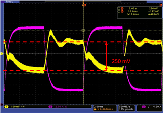
Figure 25: If load current changes from 10%(2.5A) to 60%(15A), voltage fluctuation is 290mV

Figure28:  If load current changes from 50%(12.5A) to 100%(25A), voltage fluctuation is 240mV


But the output voltage of my EVM changes 1.5V or large.

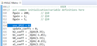
If I adjusted 2p2z coefficients in HVLLC project, but output voltage still changes around 1V.


Could you tell me 2p2z coefficients parameter when the experiment the result of figure25 and 26 can be obtained?

And are there any other points we should be careful?


Regards,

U-SK

  • Hi U-SK,

    The default 2p2z coefficients are what should have been used when capturing the transient response shown in the user guide. It sounds like you've already done this, but make sure you've set the variable use_2p2z = 1.

    Is it possible to share your scope shots so I can see what your transient response looks like? Can you zoom in enough to measure the slew rate of the current transient?

    What is your total output capacitance? The figures in the software user guide note that the output capacitance used was 2790uF, but the schematic shows less than half of that (C2+C3+C8+C9+C10+C11 = 1320uF). The output capacitance will have an impact on the transient response, so you might try adding a couple caps to get closer to the results in the user guide.

    Another thing to be careful about is the current slew rate on your electronic load. The user guide doesn't mention what slew rate was used, but it was probably 1-2 A/uS, so a higher slew rate on your load may cause more overshoot / undershoot. It will be good to confirm the current slew rate you're getting by measuring it on the scope.

    Best,

    Clayton

  • Hi Clayton,

    Thank you for your advice.

    In my environment, use_2p2z was 0, so when I changed it to 1, I succeeded in suppressing the voltage fluctuation to 426 mV by peek to peek as shown below.

    Voltage_Fluctuation_Slew_Rate.pdf

    Slew Rate of load current is 0.026A/us.

    And additional capacitors are used and total capacitance is 2790uF.

    But the settling time of output voltage after voltage fluctuation still takes around 1ms even though the TI's result takes only 208us.

    I would like to fix it.

    • Could you tell me how to configure coefficient of 2p2z in detail?
    • Or are there anything measures else to solve it?

    Regards,

    U-SK

  • Hi U-SK,

    Thank you for attaching the scope shots. Two observations:

    1. That slew rate is very slow, are you using an electronic load with an adjustable slew rate?

    2. It looks like there's about 250mV of regulation error between the 10% load and 60% load operating point. Where are you probing the voltage? Is it at the output of the power stage, or is it at the terminals of the load? This could be caused by cabling resistance if you're not measuring directly at the output of the power stage. Try probing the output voltage between the Vo and GND-S test points I've circled in the figure below.

    Please attach updated scope shots after you set the load for 1 A/uS slew rate and probe at the points I've indicated.

    Best,

    Clayton

  • Hi Clayton,

    Thank you for your advice.

    , I attached scope shots at the probe point you mentioned after configuring slew rate as below.

    Load_Fluctuation_Measurement.pdf

    But I can't achieved 1A/us due to the restrictions of the electronic load device.

    Could you give me any advices referring to above file to decrease the settling time of output voltage? 

    Regards,

    U-SK

  • Your transient response doesn't look too far off in terms of overshoot and settling time. But from your scope shots it looks like you're observing quite a bit more load regulation error than what's recorded in the user guide. You're seeing nearly 250mV from over the 10%-60% load transient, but the result in the guide (Figure 15) shows less than 100mV over the full range.

    A few questions:

    • Are you still using the original 2p2z coefficients that I showed in my first reply?
    • What is your Vin?
    • What's the regulation voltage? (Average value of Vout)
    • Can you double the e-load period so we can see a little more of the powerstage response. (Set the load current to 2.5A for 5ms, and then at 15A for 5ms) When you capture the transient response, use DC coupling for the Vout measurement, like the user guide.

    As far as tuning the transient response goes:

    • For the 2p2z controller you will probably need a plant model to tune it effectively and we haven't provided a plant model for this design. On our newer designs we use a software library to collect data from the ADCs and get an empirical model of the plant. From there you can tune the controller, but this isn't supported in these older controlSUITE projects. You may look at the newer LLC design, TIDM-1001 in the Digital Power SDK.
    • If you use the PID controller, you can more easily tune it by looking at the transient response and updating the coefficients (Kp, Ki, Kd) based on the rise time, overshoot, and stability. This procedure is described in the Digital Control Library documentation (controlSUITE\libs\control\DCL\v1_00_00_00\docs\DCL User's Guide.pdf). Manual tuning of PID controllers is a popular topic, so it is also extensively documented online.

    Below is an excerpt from the PID tuning section of "DCL User's Guide.pdf"

    Best,

    Clayton

  • Hi Clayton,

    Thank you for your advice.

    Please refer to following comment to your question.

    • Are you still using the original 2p2z coefficients that I showed in my first reply?

           →No, I'm using default value of 2p2z coefficients.

    • What is your Vin?

           →I'm using regulated DC power supply with an output of 1KVA.

    • What's the regulation voltage? (Average value of Vout)

      →Average value of Vout was 12.0V.(Please refer to below attached file)

    • Can you double the e-load period so we can see a little more of the powerstage response. (Set the load current to 2.5A for 5ms, and then at 15A for 5ms) When you capture the transient response, use DC coupling for the Vout measurement, like the user guide.

          →I measured signals at doubled and half of e-load period. Please refer to below attached file.

    5367.20210325_Voltage_Fructuation.pdf

    And I will also consider using PID turning.

    Are there any other improvements?

    Regards,

    U-SK

  • Hi U-SK,

    Please let me look at this question and get back to you with a couple more suggestions by end of day tomorrow (US Central Time).

    Best,

    Clayton

  • Hi U-SK,

    Sorry for the delay.

    It's possible some of the regulation error in the figures you've shared is from the 2p2z controller. If one of the compensator zeros gets too close to the zero frequency pole, then it can start to cancel the integrator and introduce steady-state error. If you want to use the 2p2z controller, I think you will need to try to address this issue by changing the tuning. Otherwise, I recommend using the PID controller in your case because it will be easier to tune based on characteristics of the transient response as I described above.

    Best,

    -Clayton

  • Hi Clayton,

    Thank you for your reply.

    I'm considering using PID controller of DCL, but it seems not to support TMS320F2803x because it does not have FPU.

    And closed loop demo on TMDSHVRESLLCKIT seems to use PID controller and convert it to 2p2z controller, so is my understanding as below correct?

    ・use_2P2Z=0 //(use PID instead of 2p2z)

    ・Configure Pgain, Igain, and Dgain referring chapter 3.3 in DCL user guide 

    Regards,

    U-SK

  • Hi Clayton,

    Do you have any updates?

    Regards,

    U-SK

  • Hi U-SK,

    Sorry, I was out of office the passed week and missed your posts.

    What you've described is a fine way to proceed.

    Best,

    Clayton